How-Tos
- How to configure DTMF action
- How to create a call sequence (Dial to multiple numbers)
- How to create a call group (Dial to multiple numbers)
- How to configure outgoing call routes
- How to start a packet capture
- How to configure callHandling based on a received buttonpress from an intercom
- How to add an entry (relation) to SearchAndFind, including callHandling/forwarding
- How to configure alternate rules/forwards when dialing to a relation/contact.
- How to apply a theme to the CoCoS management Environment
- How to control an Output on a MOXA ioLogik using the CoCoS MOXA connector
- How to control an Output on a MOXA ioLogik using a CoCoS Script
- How to Control a Relay on a Commend ET908H SIP using a CoCoS Script
- How to configure IAX Connection
How to configure DTMF action
Description
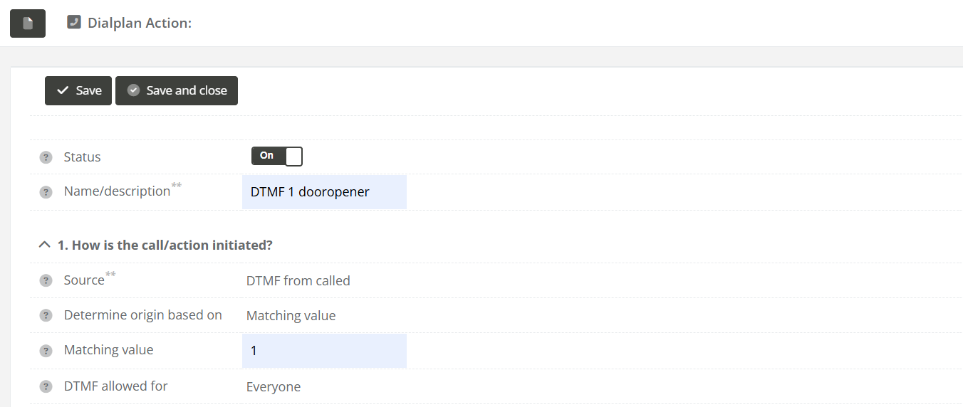
This guide describes how to configure a DTMF (Dual-Tone Multi-Frequency) action on an intercom station. A DTMF action allows the system to respond to specific keypad input from the called party—for example, to trigger a script such as opening a door or updating a tag value during a call.
Application
This configuration is typically used in intercom systems where certain user inputs (e.g., pressing "1" during a call) need to trigger specific automated actions. A common use case involves opening a door remotely when a correct DTMF digit is received from the called party.
How To
| Step 1: Navigate to "System / Devices", and open the intercom station for which you want to configure a DTMF action for. | |
| Step 2: Navigate to the "Call-Handling" tab, and click on the new dialplan action button under "2. Actions for this station". |
|
|
Step 3: Fill in the following fields:
|
|
|
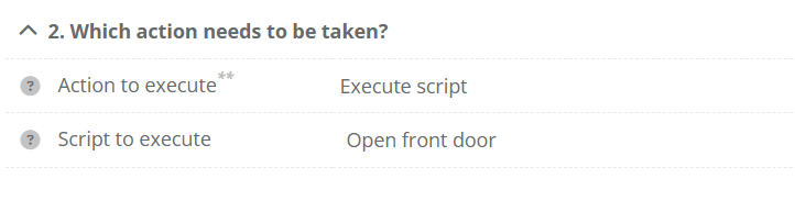
Step 3 (for executing Script): For |
|
|
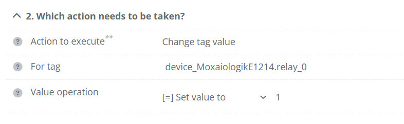
Step 3 (for setting a tag): For
Note: For "Moxa ioLogik" devices we can set the tag to a milliseconds amount for a pulse. For example setting the tag to "3000" will set the output high for 3 seconds.
|
|

How to create a call sequence (Dial to multiple numbers)
Description
Dialing to a callgroup (multiple numbers in) a nut shell
In CoCoS it's possible to configure calling to multiple intercom and phone-numbers in 3 different way's:
- Sequences
- Group call : first to answer
- Group call : conference call.
In addition to the calls, we also have all-call for and selective selective-call for PA systems.
Case description call sequence
A call sequence makes it possible to dial to multiple numbers one by one. Visualized a sequences looks like this:

How To Create A Sequence
IMPORTANT NOTE REGARDING NESTED SEQUENCES AND GROUPS
Nested call groups a not configurable for CoCoS versions lower then v5.2. It's not possible to use sequences in groups and vice versa. Although it's already configurable in CoCoS, the intercomservers that have to execute a nested sequence or group cannot handle the complexity of such instruction (yet).
|
Step 1
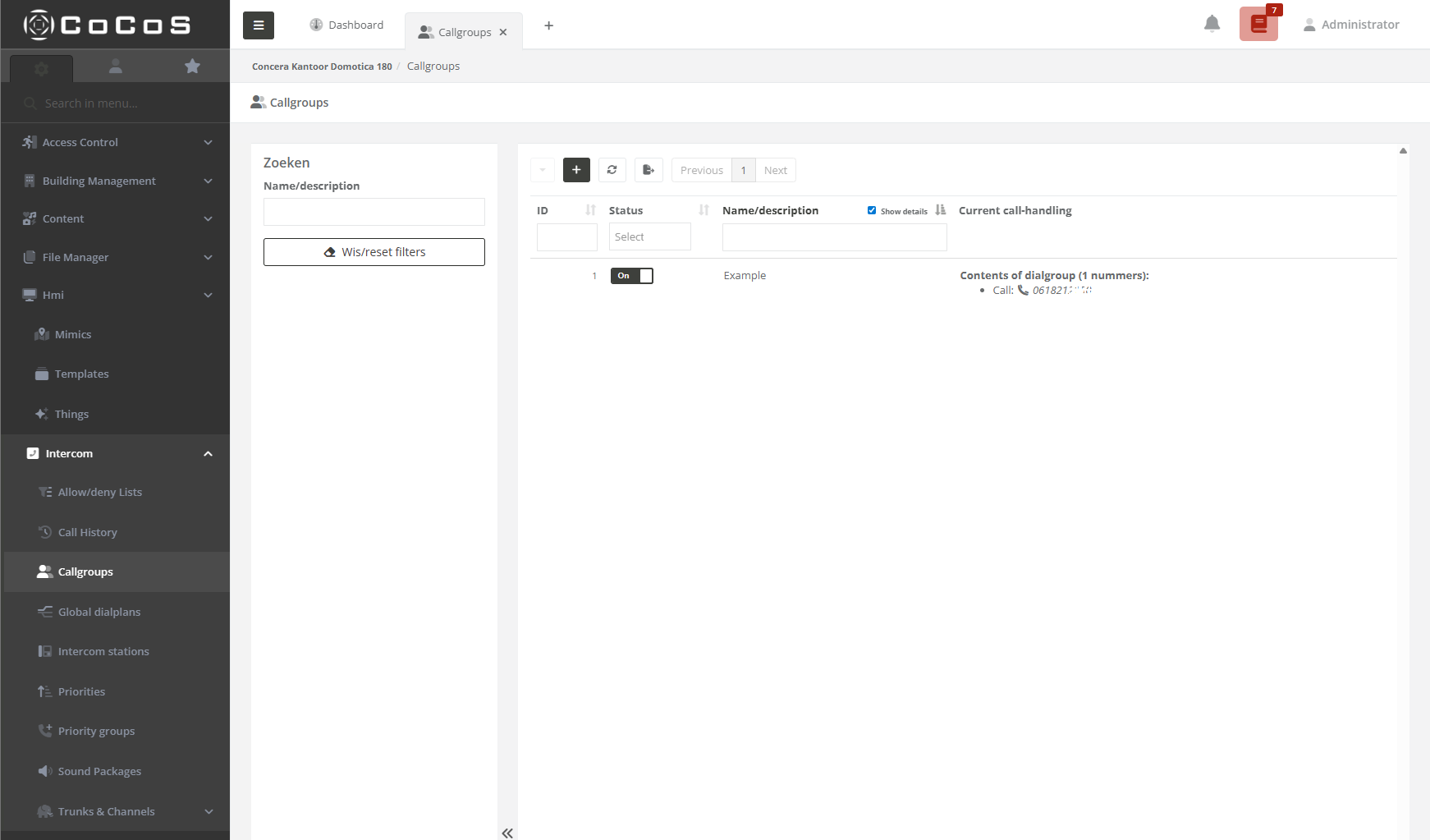
Open the callgroup manger in the intercom menu. |
|
|
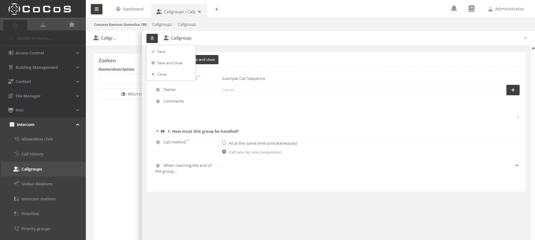
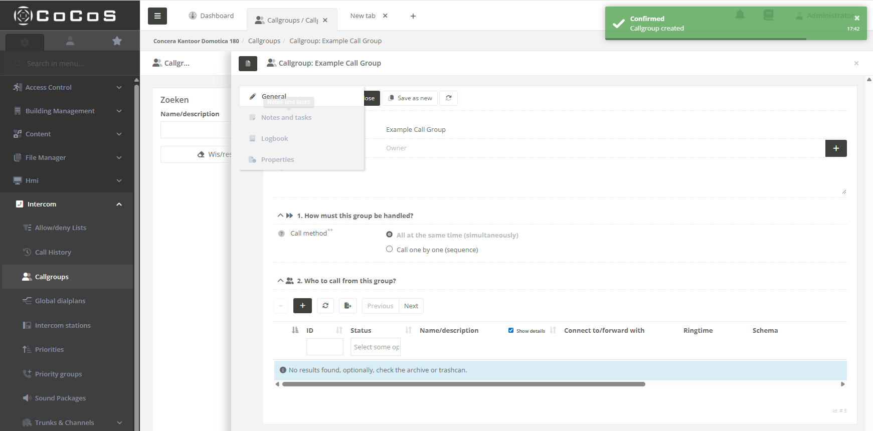
Step 2 Click the [ + ] button to create a new call-group. Enter a name (in the example we use exmaple call sequence) and select what type of call-method is used. In this case we use the "Cal one by one (sequence)" and then press [ Save ] |
|
|
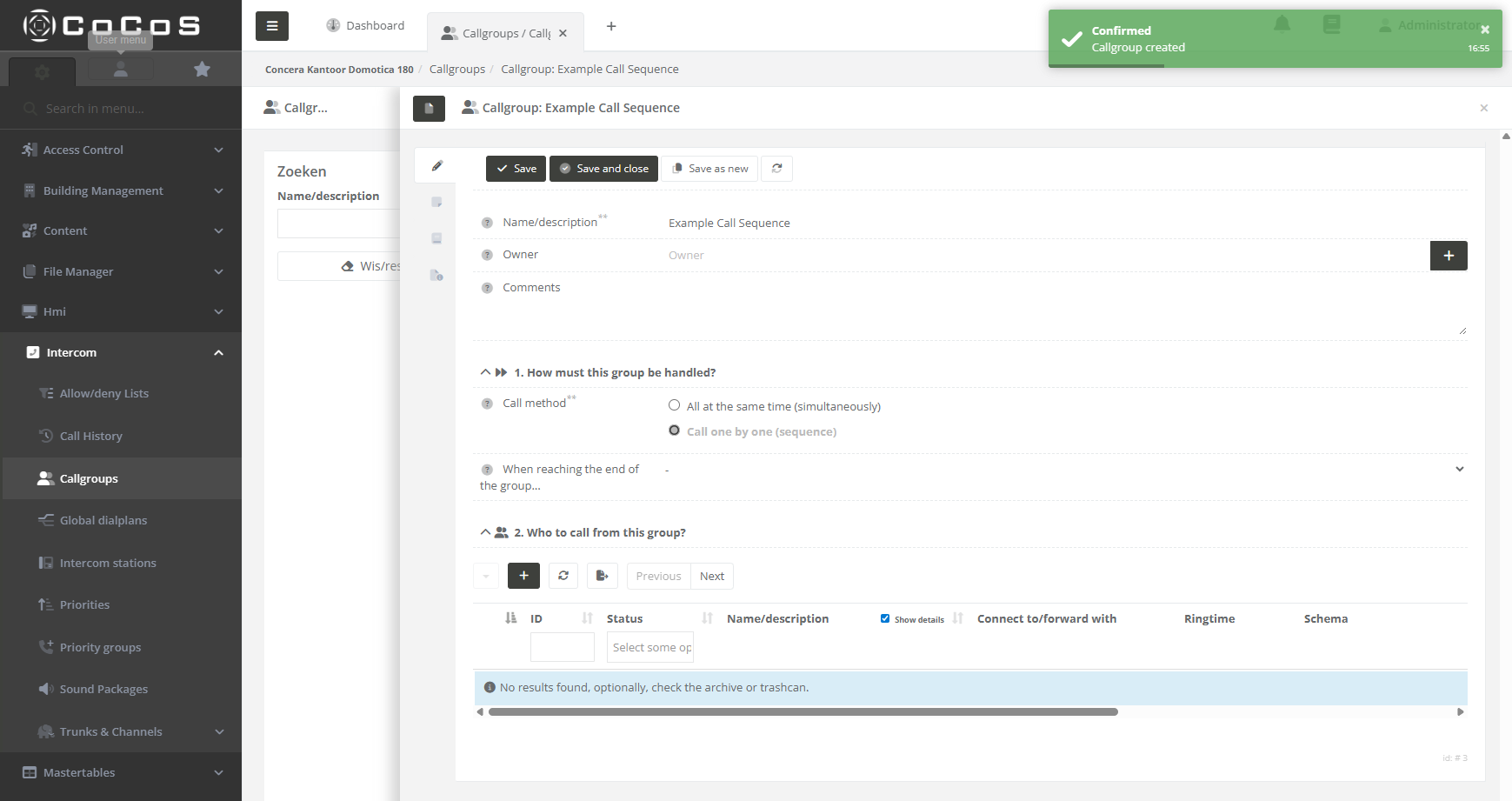
When saved, the system will confirm the creation of the group by displaying the editor for adding the receiving (target) intercom or phone devices.
|
|
|
Step 3
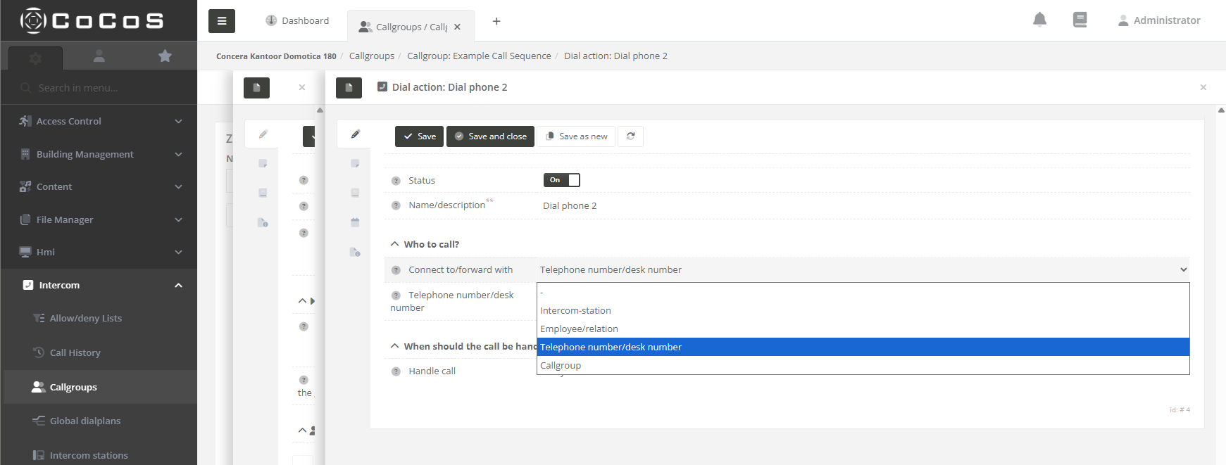
To add a target, simply click the [ + ] button and complete the form. Only the Name and "Who to Call" fields are required. The remaining options will be explained in the following paragraphs.
|
|
|
The next step is to add all targets required for the call sequence. You may use:
Note that the option "Call Group" as target is not yet supported up till version 5.0, nested call groups a available from version 5.2
|
|
|
Step 4
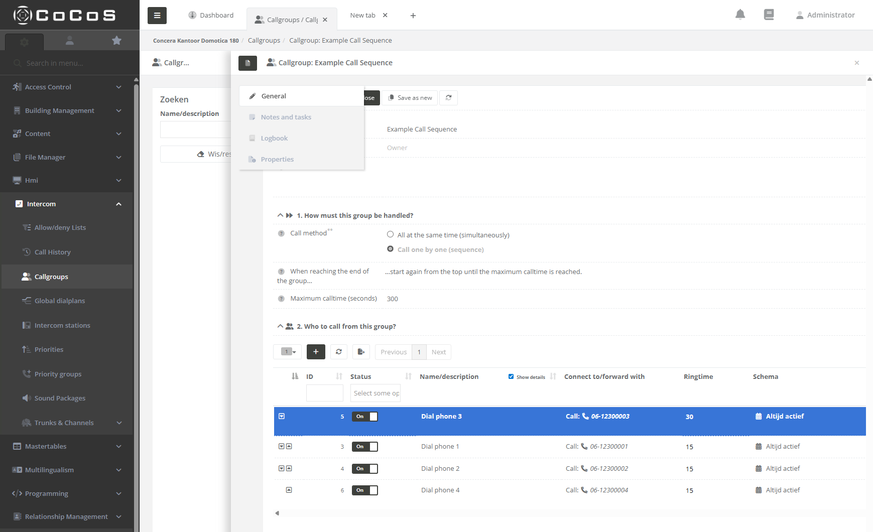
Once all targets are entered, you can configure the ring time for each target and, if necessary, adjust their order. In our example, we moved Phone 3 to the top of the sequence and set its ring time to 30 seconds. The sequence is now as follows:
Since we selected the option "Start again from the top until the maximum call time of 300 seconds is reached," the sequence will repeat from the beginning until a call is answered or the 300 second limit is reached.
When ready, hit [ save and close ] |
|
|
|
|

Custom Settings
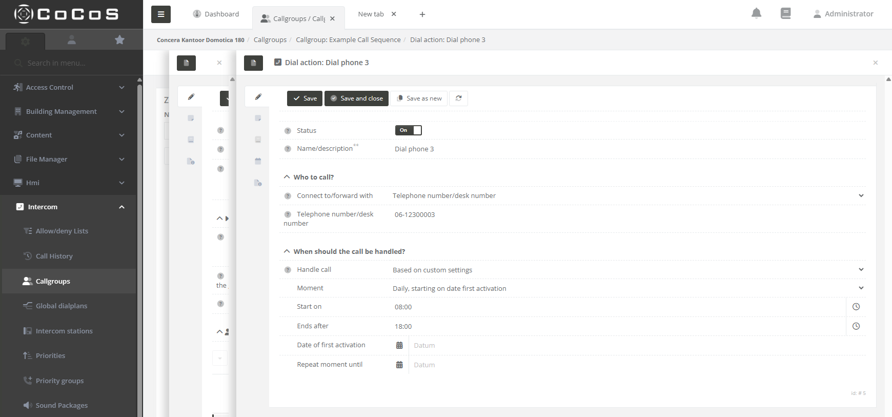
It's possible to add some conditions to the target when configured in the sequence. We can select "Based on custom settings" in the "Handle call" setting.
|
Daily, starting on date first activation
The target is only enabled in the call sequence if the date and time match the configuration.
This means the target will be active every day, starting from the first activation date, until the repeat-until date is reached (if specified).
|
|
|
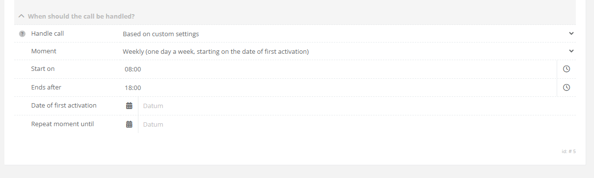
One day a week starting on the date of first activation.
The weekly schedule also begins on the date of first activation. For example, if the first activation occurs on a Wednesday, the target will be enabled every Wednesday thereafter.
If a "Repeat Until" date is configured, the target will automatically be disabled in the sequence once that date is reached.
|
|
|
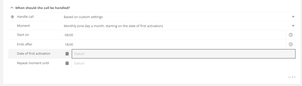
One day a month starting on the date of first activation.
The monthly schedule begins on the date of first activation. For example, if the activation date is the 13th of the month, the target will be enabled on the 13th of every subsequent month.
The schedules takes the real day of the month, so take in mind that not every month has the same number of days.
|
|
|
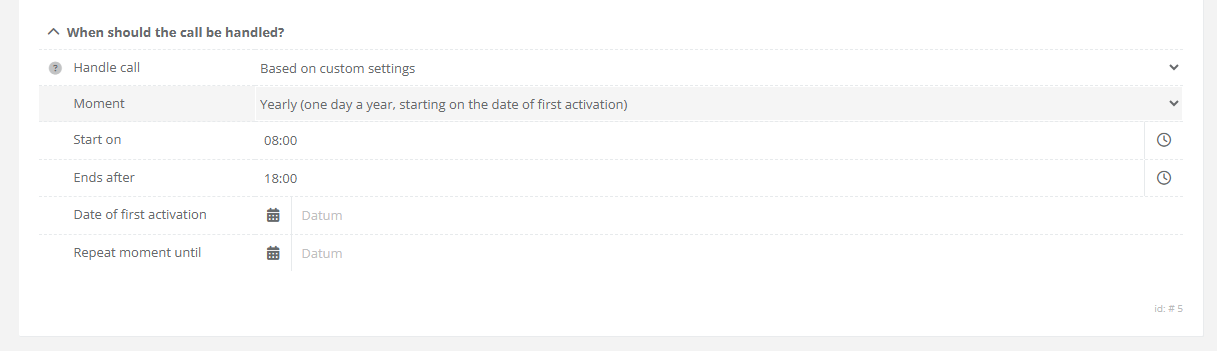
One day a year starting on the date of first activation.
This schedule can be use for configuring fixed holiday's for example. Take chrismas or new years day.
If a "Repeat Until" date is configured, the target will be disabled in the sequence after that date is reached.
|
|
|
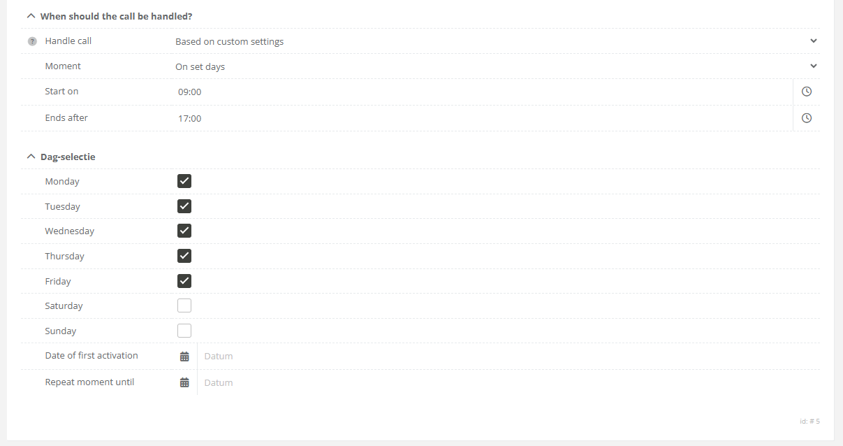
On set days.
Use this scheduling option whenever a specific target (for example the reception of an office) needs to be included in the secuence on work days.
In the example we configured the target to be enabled in the sequence from monday to friday from 9:00 till 17:00. |
|
|
|
|
References
Related articales:
Dail to multiple numbers - creating a call group
How to create a call group (Dial to multiple numbers)
Description
Dialing to a callgroup (multiple numbers in) a nut shell
In CoCoS it's possible to configure calling to multiple intercom and phone-numbers in 3 different way's:
- Sequences
- Group call : first to answer
- Group call : conference call.
In addition to the calls, we also have all-call for and selective selective-call for PA systems.
Case description call group
A call group makes it possible to dial to multiple numbers at once. Visualized a group call looks like this:

How To Create A Call Group
IMPORTANT NOTE REGARDING NESTED SEQUENCES AND GROUPS
Nested call groups a not configurable for CoCoS versions lower then v5.2. It's not possible to use sequences in groups and vice versa. Although it's already configurable in CoCoS, the intercomservers that have to execute a nested sequence or group cannot handle the complexity of such instruction (yet).
|
Step 1
Open the callgroup manger in the intercom menu. |
|
|
Step 2 Click the [ + ] button to create a new call-group. Enter a name (in the example we use example call group) and select what type of call-method is used. In this case we use the "All at the same time (simultaneously)" and then press [ Save ] |
|
|
When saved, the system will confirm the creation of the group by displaying the editor for adding the receiving (target) intercom or phone devices.
|
|
|
Step 3
To add a target, simply click the [ + ] button and complete the form. Only the Name and "Who to Call" fields are required. The remaining options will be explained in the following paragraphs.
|
|
|
The next step is to add all targets required for the call group. You may use:
Note that the option "Call Group" as target is not yet supported up till version 5.0, nested call groups a available from version 5.2
|
|
|
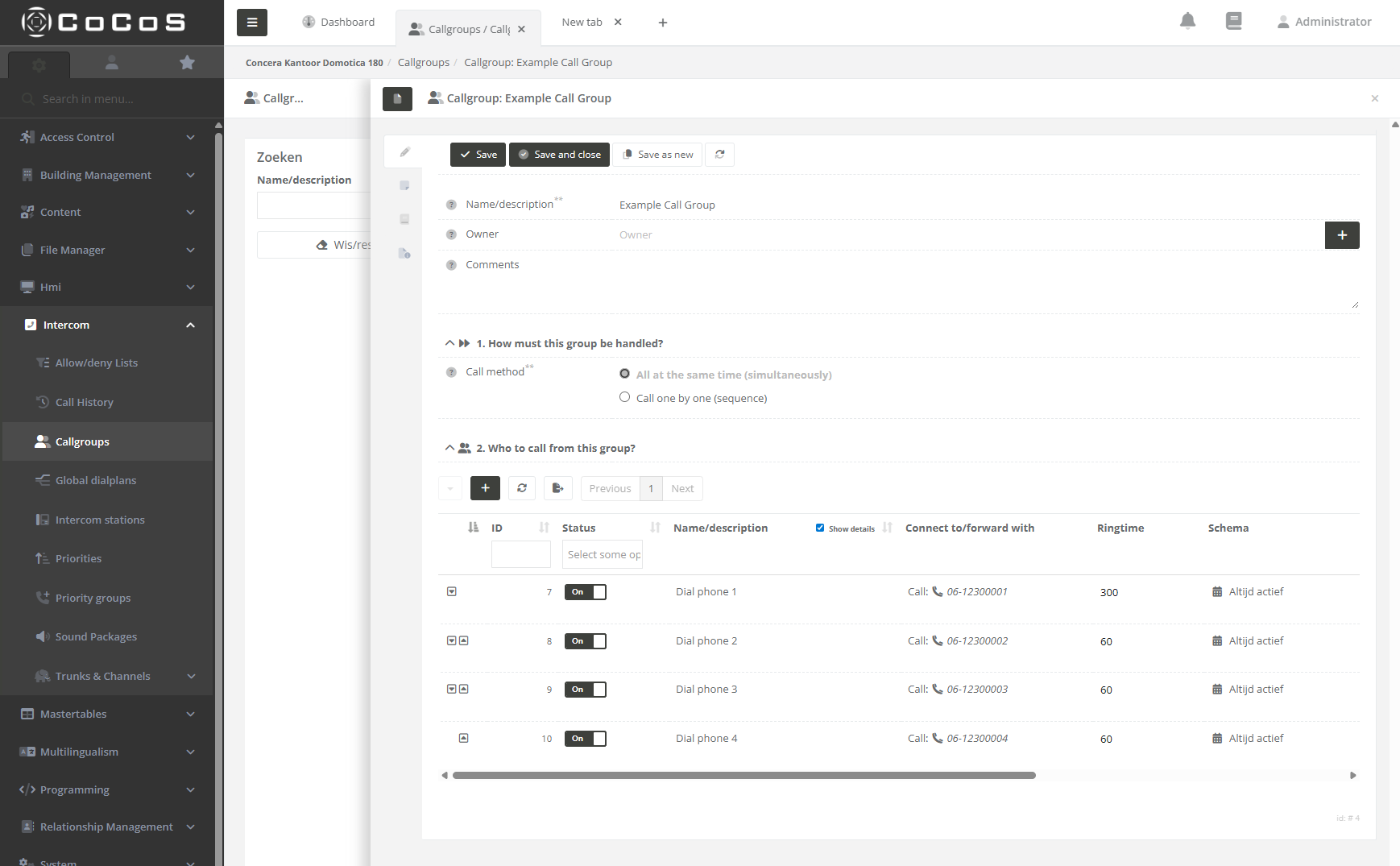
Step 4
Once all targets are entered, you can configure the ring time for each target. When the call group is activated all targets are dialed simulaniously. Every target has it's own maximum ringtime. In the configured exmaple, after 60 seconds phone 2, 3 and 4 will stop ringing and only phone 1 will continue to ring.
When the configuration meets the requirements, hit [ save and close ] |
|
|
|
|
Custom Settings
It's possible to add some conditions to the target when configured in the group. We can select "Based on custom settings" in the "Handle call" setting.
|
Daily, starting on date first activation
The target is only enabled in the call group if the date and time match the configuration.
This means the target will be active every day, starting from the first activation date, until the repeat-until date is reached (if specified).
|
|
|
One day a week starting on the date of first activation.
The weekly schedule also begins on the date of first activation. For example, if the first activation occurs on a Wednesday, the target will be enabled every Wednesday thereafter.
If a "Repeat Until" date is configured, the target will automatically be disabled in the group once that date is reached.
|
|
|
One day a month starting on the date of first activation.
The monthly schedule begins on the date of first activation. For example, if the activation date is the 13th of the month, the target will be enabled on the 13th of every subsequent month.
The schedules takes the real day of the month, so take in mind that not every month has the same number of days.
|
|
|
One day a year starting on the date of first activation.
This schedule can be use for configuring fixed holiday's for example. Take chrismas or new years day.
If a "Repeat Until" date is configured, the target will be disabled in the group after that date is reached.
|
|
|
On set days.
Use this scheduling option whenever a specific target (for example the reception of an office) needs to be included in the secuence on work days.
In the example we configured the target to be enabled in the group from monday to friday from 9:00 till 17:00. |
|
|
|
|
References
Related items
How to create a call sequence (Dial to multiple numbers)
How to configure outgoing call routes
Question or Case description
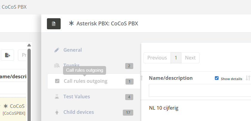
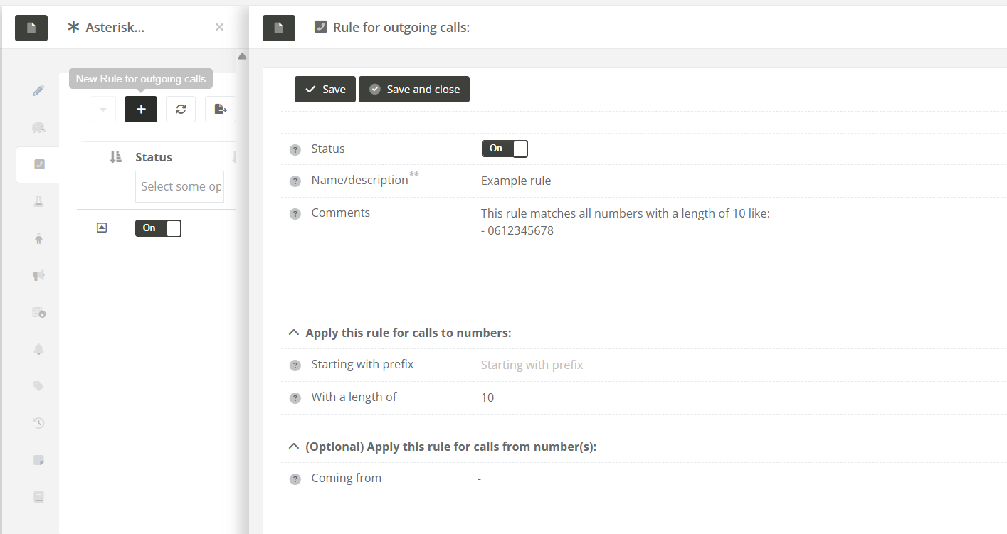
To make outbound (external) calls through your PBX system, you need to configure outgoing call rules. These rules define which calls should go out (for example, calls to 10-digit numbers) and which trunk (connection to the outside phone network) should be used.
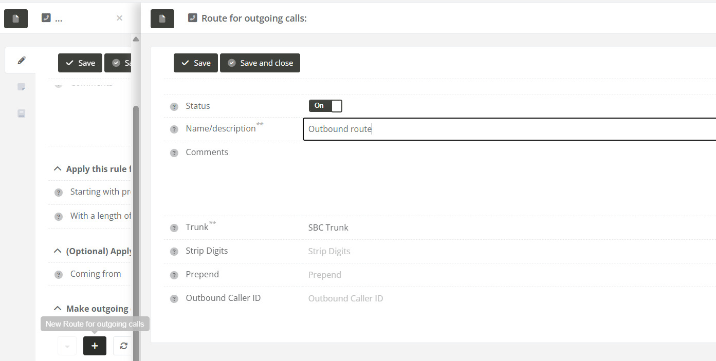
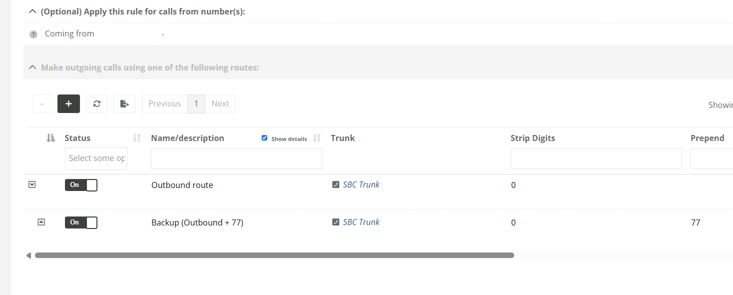
Each rule can have one or more routes. A route tells the system which trunk to use for the outgoing call. You can also adjust the number before sending it out (for example, by removing or adding digits). If the first route fails, backup routes can be used automatically.
This manual explains how to set up outgoing call rules and attach one or more routes to them.
Solution / Resolution / How To
Describe how to fix it, how to validate an observation or describe how to configure a specific case. Only use one title, solution, resolution or How-to
|
|
|
|
|
|
|
|
|
|
|
|
Tips
- Routes are tried in the order they appear. If one route fails, the next one is used.
- Keep your matching rules specific to avoid sending calls to the wrong trunk.
How to Identify and Fix Problematic Call Rules
In the Outgoing Call Rules overview, you may sometimes see warnings or errors next to certain rules. These indicate that a rule isn't working properly and will be skipped when trying to place an outgoing call.
These issues are clearly marked using icons and colors:
-
Warning (⚠️) – Something is missing, but the rule might still work under certain conditions.
-
Error (🚫) – The rule is not usable and will be completely skipped.
Note: When a rule has an error icon (🚫), it will be ignored entirely by the system when trying to place a call.
Below are the most common warning and error types, how to recognize them, and how to resolve them.
1. No outbound routes
Description: The rule does not have any routes configured. Without routes, the system doesn't know how to send the call out.

How to fix: Edit the rule and add at least one valid outbound route.
2. Outbound route(s) in error
Description: One or more routes use a trunk that is unavailable or has an error.

How to fix: Check the status of the trunk(s) and fix any connection issues. You can also assign another working trunk to the route.
3. Invalid source device
Description: The device listed under "Coming from" is turned off or currently in an error state.

How to fix: Make sure the source device is online and functioning correctly.
Test & Validate
After fixing any of the above issues:
- Refresh the Outgoing Call Rules list.
- Verify that the icons and color warnings are gone.
- Place a test call to confirm the rule works correctly.
How to start a packet capture
Description
This article explains how to start, stop, and download a packet capture within the CoCoS platform.
A packet capture allows you to record network traffic so you can analyze protocols such as SIP and RTP. Packet captures are often used to diagnose call quality issues, signalling behaviour, or general network irregularities.
Application
Packet captures are typically used when analyzing network behaviour.
Examples include:
-
Verifying SIP signalling sequences
-
Inspecting RTP audio streams
-
Identifying latency, jitter, or packet loss indicators
-
Troubleshooting firewall or routing behaviour
How To
Packet captures can be created directly from the Network section in CoCoS. The steps below explain how to perform a quick capture or how to configure a custom capture.
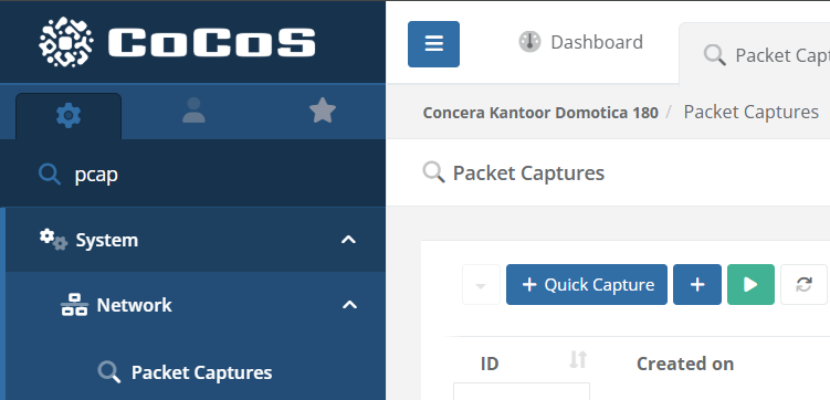
| Step 1: Open the Packet Capture page Navigate to System → Network → Packet Captures in the CoCoS application menu. |
|
|
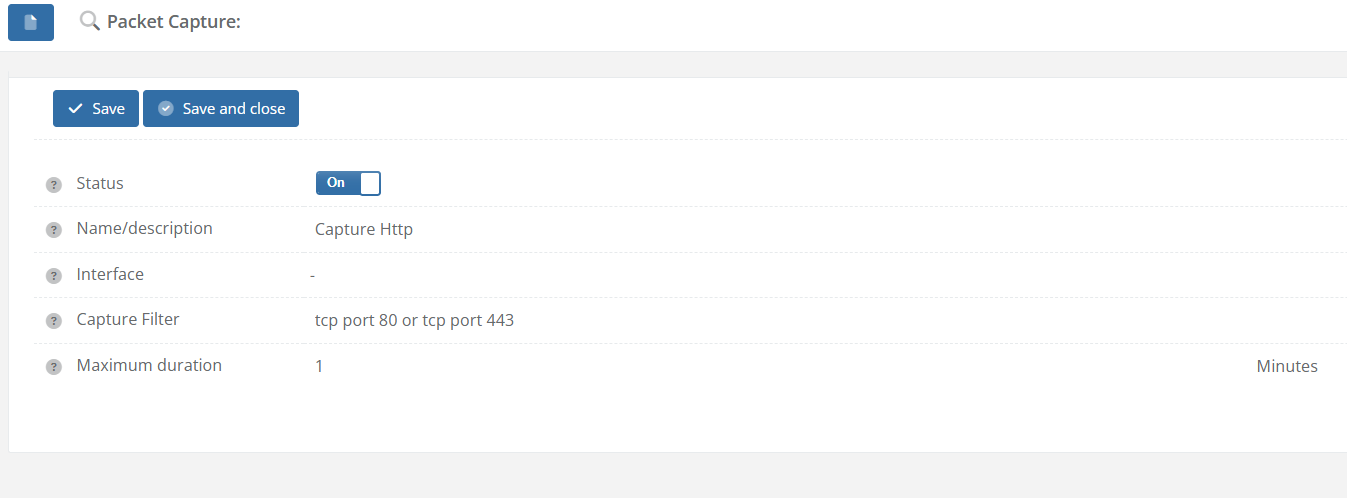
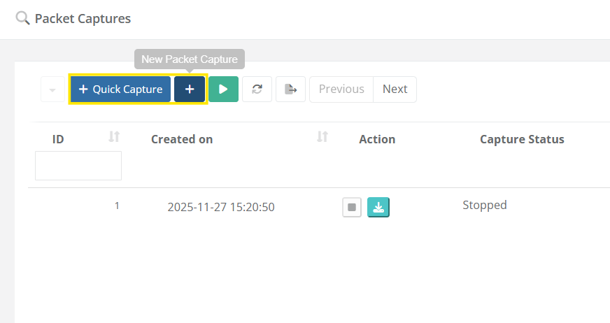
Step 2: Start a capture
|
|
| Step 3: Stop the capture Once the capture has started, use the Stop action to end the recording. Captures can run until manually stopped or until predefined limits are reached. |
|
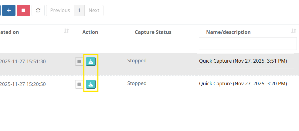
| Step 4: Download the capture After the capture has stopped, click the Download action to save the capture file. The downloaded file can be opened with standard analysis tools such as Wireshark. |
|

How to configure callHandling based on a received buttonpress from an intercom
Question or Case description
This guide describes how to configure CoCoS in order to handle a buttonpress, received from an intercom-station. Based on the received buttonPress, a dialplan/dialrule can be created, use to specify which contact (relation) needs to be called.
Prerequisites
On this page, we'll only cover the configuration in CoCoS and therefore assume that the intercom-station is configured correctly, in order to send a button-press to CoCoS.
How To
Before you start, please keep in mind: When configuring a call-action for a button at a intercom station (using a global diaplan), create only 1 rule per button. When schedules or more advanced options are nessecary to create conditions based on which the call has to be forwarded elsewhere, configure this as the relation used as target (forward to) for the buttonpress.
See page: How-to configure alternate rules/forwards when dialing to a relation/contact at https://knowledgebase.cocos.software/books/cocos-knowledgebase/page/how-to-configure-alternate-rulesforwards-when-dialing-to-a-relationcontact.
For a single intercom station:
| Step 1: Navigate to "Intercom / Intercom stations" or "Intercom / configurations" and open the intercom station for which you want to handle a received buttonpress. | |
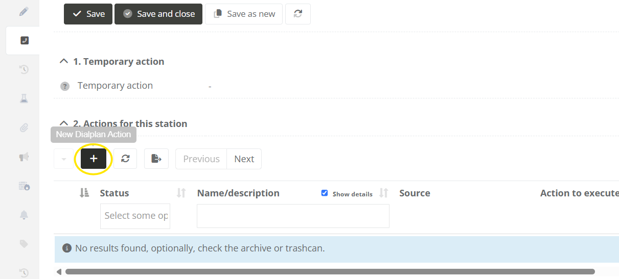
| Step 2: Navigate to the "Call-Handling" tab, and click on the new dialplan action button under "2. Actions for this station". |
|
|
Step 3: Fill in the field for the diaplan action. In section "1. How is the call/action initiated?", choose the following options:
|
|
|
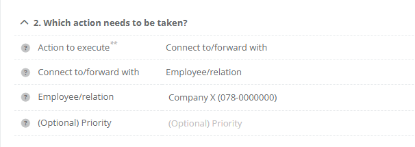
Step 4: In section "2. Which action needs to be taken?", choose the following options:
|
|
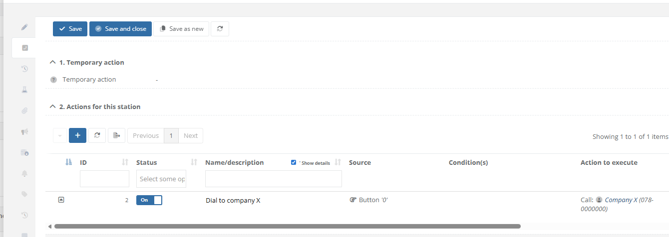
| Step 5: Save the dialplan action. Tab "Call-Handling" at the intercom station will now display that "Company X" is called when button 0 is pressed at the intercom station. |
|
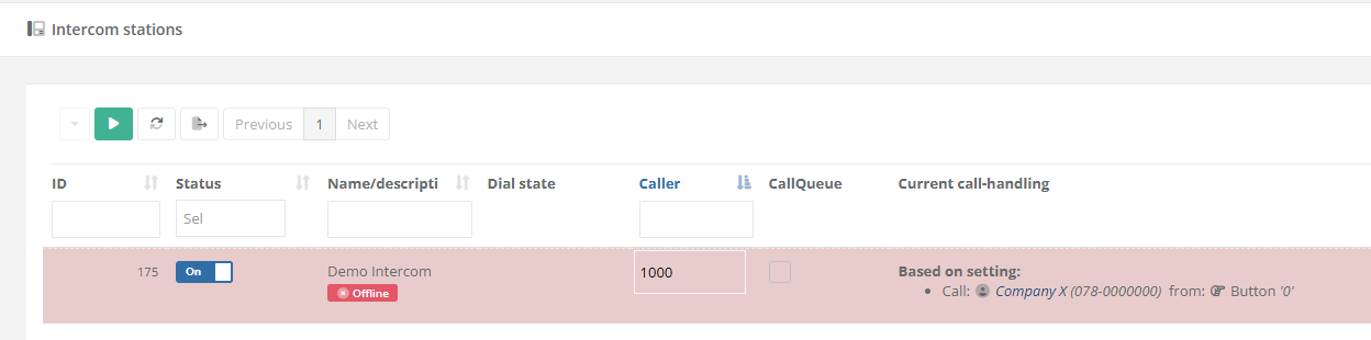
| Step 6: After saving and closing the Intercom Station, the list with all devices will display the configuration in column "Current call-handling". The custom action will be dispayed wuith the text "Based on setting". |
|


For a multiple intercom-stations:
When multiple intercom stations at a site/location all require the same configuration, a "Global dialplan" can be used. This way, the same configuration can be applied to multiple devices simultaneously.
|
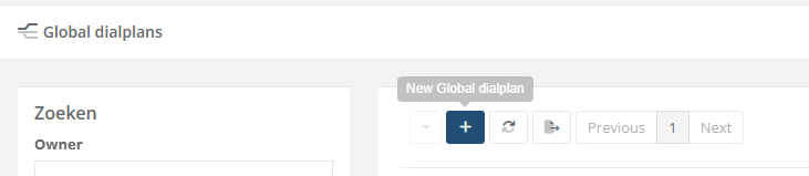
When no global dialplan is available yet, create and configure a new one. Otherwise, continue directly with step 6. |
|
|
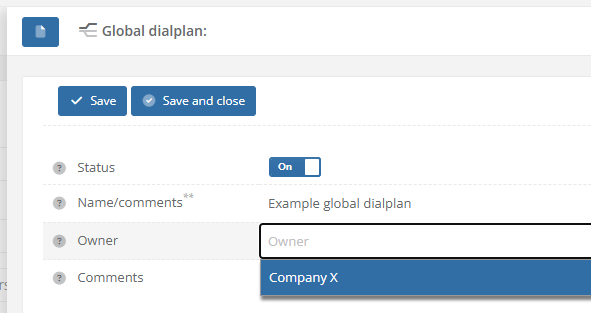
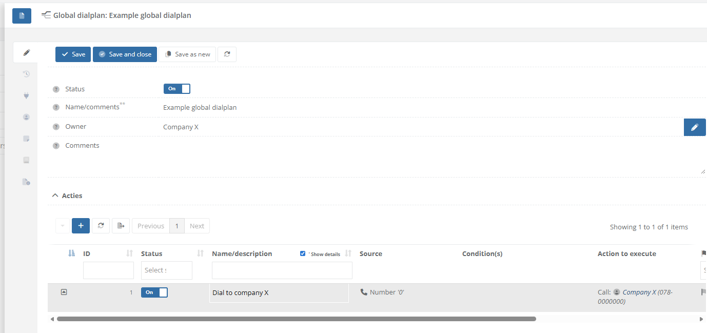
Step 2: Create a new dialplan by giving it a name. Optionally, select the owner/relation is belongs to. |
|
|
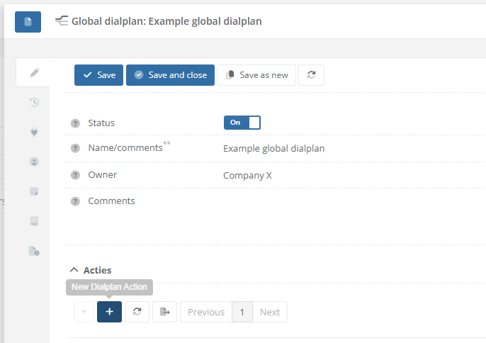
Step 3: After saving the Global dialplan. Use the [ + ] sign in the list with actions in order to add a new new rule. |
|
|
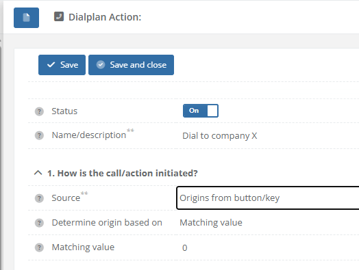
Step 4: Fill in the field for the diaplan action. In section "1. How is the call/action initiated?", choose the following options:
|
|
|
Step 5: In section "2. Which action needs to be taken?", choose the following options:
|
|
| Step 5: Save the dialplan action. The list with "Actions" at the global dialplan will now display that "Company X" is called when button 0 is pressed. |
|
|
Step 6: Navigate to "Intercom / Intercom stations" or "Intercom / configurations" and open the intercom station for which you want to handle a received buttonpress. |
|
|
Step 7: Navigate to the "Call-Handling" tab. In section "3. Global dialplan", select which the dialplan to use. |
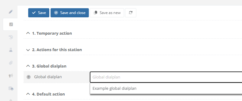 |
| Step 8: After saving and closing the Intercom Station, the list with all devices will display the configuration in column "Current call-handling". The custom action will be dispayed wuith the text "Based on dialplan". |
|
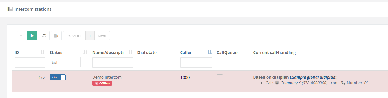
Based on the examples above, the relatinon "Company X" willl be called when button 0 is pressed at the intercom station(s).
When schedules or more advanced options are nessecary to create conditions based on which the call has to be forwarded elsewhere, configure this as the relation used as target (forward to) for the buttonpress. See page: How-to configure alternate rules/forwards when dialing to a relation/contact at https://knowledgebase.cocos.software/books/cocos-knowledgebase/page/how-to-configure-alternate-rulesforwards-when-dialing-to-a-relationcontact.
References
-
How to add an entry (relation) to SearchAndFind, including callHandling/forwarding
Question or Case description
This guide describes how to add an entry (relation) onto a SearchAndFind system. When a call is started, a dialplan/dialrule can be created, use to specify which contact (relation) needs to be called, for example based on a schedule.
Prerequisites
This page only convers adding relationships to an existing installation and therefore assume that a working SearchAndFind configuration (linked to a location) is already present in CoCoS.
How To
| Step 1: Navigate to "Relationships / Relations". Optionally, when dealing with hierarchy, open the existing relation the relation to create belongs to. | |
| Step 2: Use the [ + ] button from the list (or sublist) in order to create a new relation. | 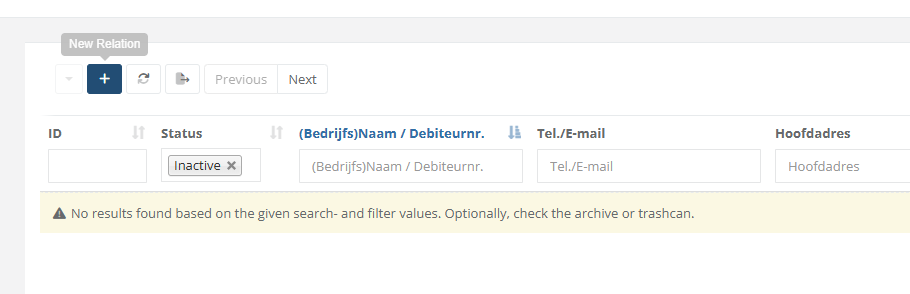 |
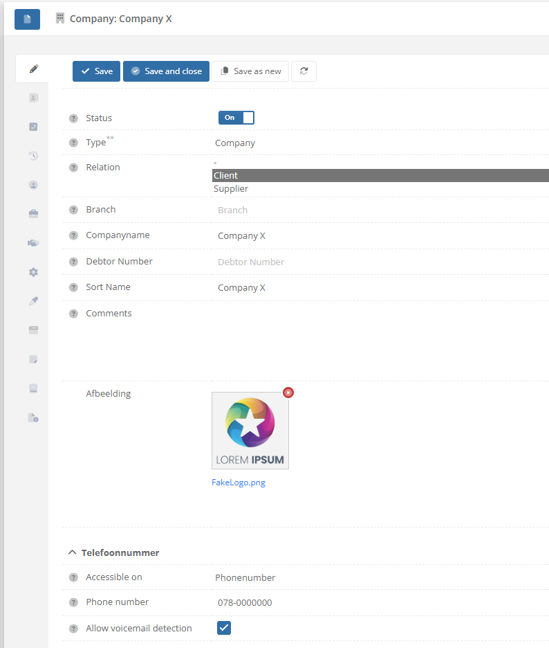
| Step 3: Fill in the fields like name, phonenumber and upload a logo/icon for the contact. |
|
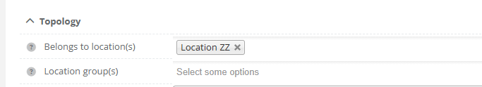
| Step 4: In section/tab "Topology", select which location(s) the relation has to be displayed. SearchAndFind devices configured/linked onto the same location, will display the associated relations for them. |
|
|
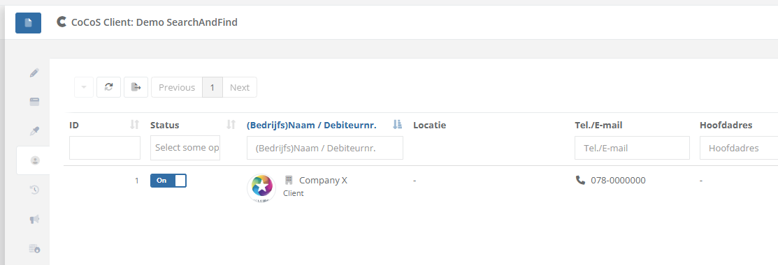
Step 5 / Test: Navigate to "System / Devices" and open the SearchAndFind device(s) on which the relation should be displayed on.
In the tab "Relationships", the CoCoS management already displays which relations will be available to display. |
|
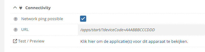
| Step 6 / Test: In tab "General", use the "Test/Preview" link to view the SearchAndFind application. |
|
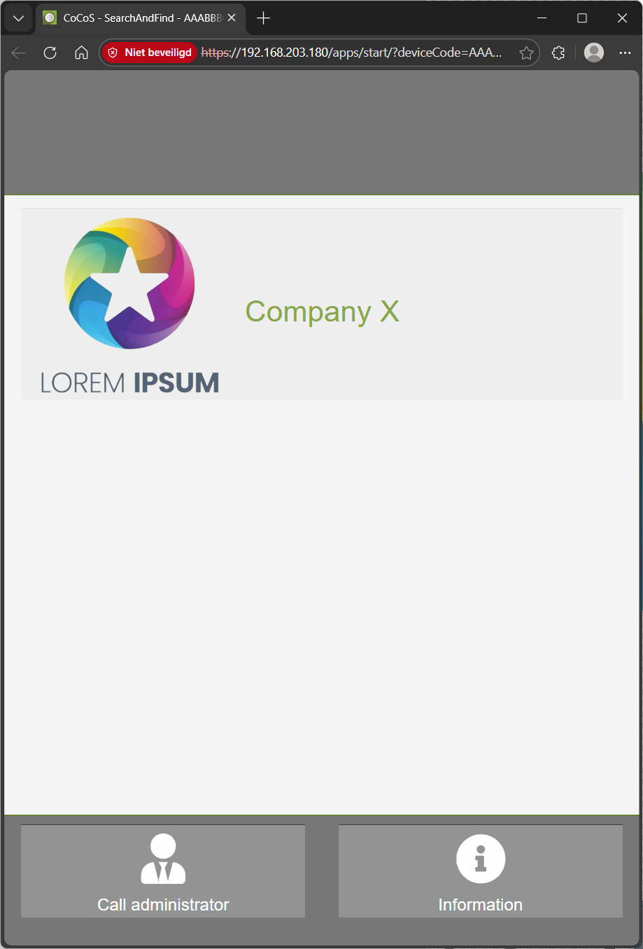
Based on the example above, the relatinon "Company X" willl be called when it's being pressed/touched at the SearchAndFind application.
When schedules or more advanced options are nessecary to create conditions based on which the call has to be forwarded elsewhere, configure this as the relation used as target (forward to) for the buttonpress. See page: How-to configure alternate rules/forwards when dialing to a relation/contact at https://knowledgebase.cocos.software/books/cocos-knowledgebase/page/how-to-configure-alternate-rulesforwards-when-dialing-to-a-relationcontact.
References
-
How to configure alternate rules/forwards when dialing to a relation/contact.
Question or Case description
This guide describes how to configure a relation/contact at CoCoS, so schedules or more advanced options can be used to create conditions based on which a call to a relation has to be forwarded elsewhere. The call to a relation can be initiated by, for example, a buttonpress at an intercom station (see also: https://knowledgebase.cocos.software/books/cocos-knowledgebase/page/how-to-configure-callhandling-based-on-a-received-buttonpress-from-an-intercom) or an action from a SearchAndFind application (see also: https://knowledgebase.cocos.software/books/cocos-knowledgebase/page/how-to-add-an-entry-relation-to-searchandfind-including-callhandlingforwarding).
When nothing is configured at a relation, the callHandling will be straight forward: When the call is initiated, the relation will be called on the configured number. By adding exceptions, under certain conditions such as a schedule, it is possible to exclude calls from the relation and forward them elsewhere.
How To
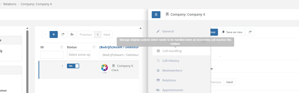
| Step 1: Navigate to "Relationships / Relations". Optionally, when dealing with hierarchy, open the existing relation the relation to create belongs to or use the search field in the header of the main list to find the relation. | |
| Step 2: Open the relation and nativate to tab "Call handling" to add custom dial plan rules/actions for the relation. |
|
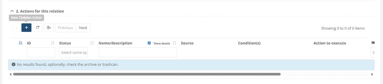
| Step 3: Use the [ + ] button under "2. Actions for this relation" to add a new action. |
|
|
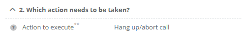
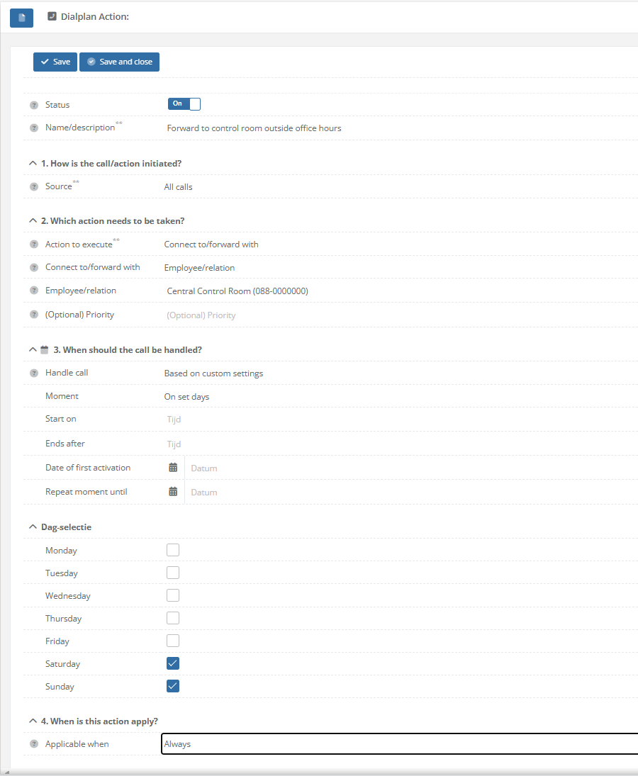
Step 4: Configure the dial plan action based on the desired funtionality. This can be:
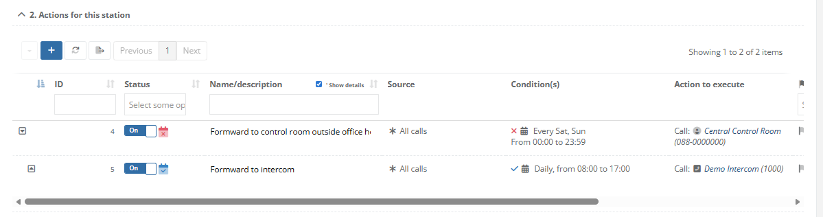
In the example, we configure to forward calls to a Central Control Room (Dutch: Meldkamer) on set days, in this case Saterday and Sunday
* Besides forwarding, it's also possible to select option "Hang up/abort call", like in the example below:
|
|
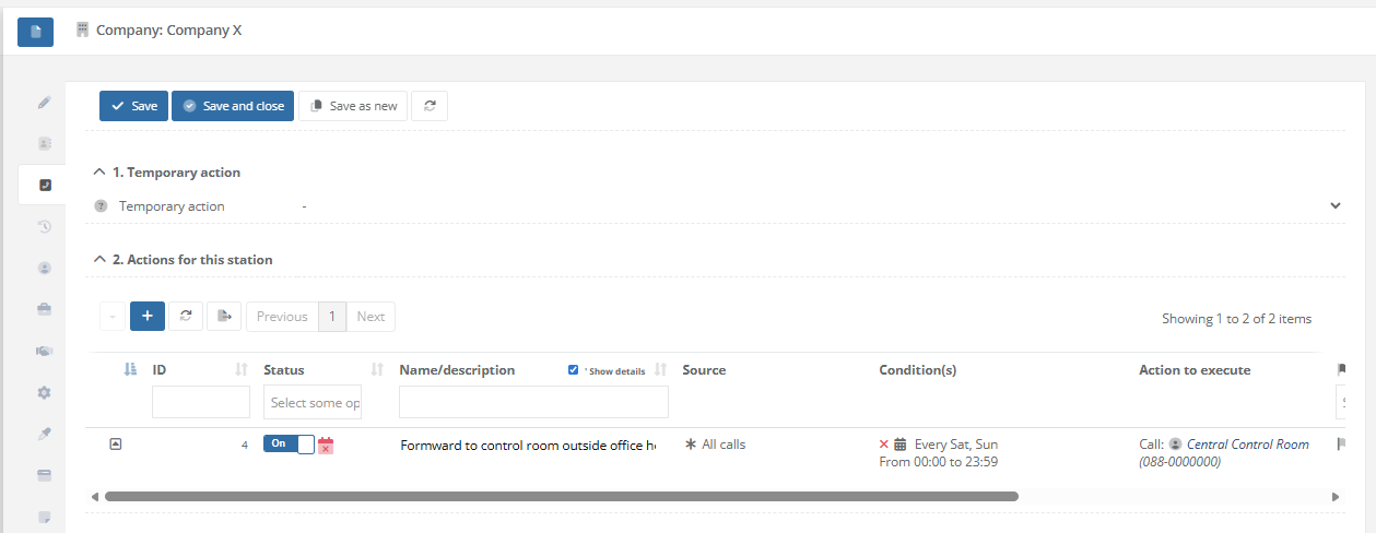
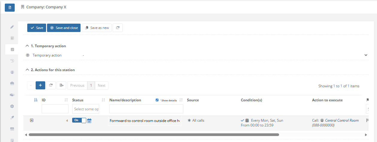
| Step 5: Save the dialplan action. Tab "Call-Handling" at the relation will now display that "Central Control Room" is called every Saterday and Sunday. The calendar icons at the start of the row indicate whether or not the rule is active. When the icon is red, this means the schedule doesn't meet the current date/time, so the rule won't be executed/handled. When the icon is blue, this means the schedule meets the current date/time, and the rule will be executed/handled (if no other conditions are specified). |
|
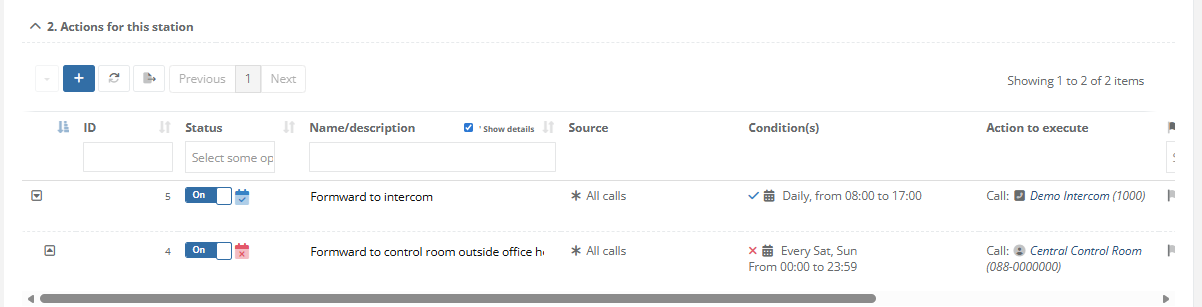
| When adding multiple rules, the first rule that matches the specified conditions will be executed. By ordering the rules using the arrows (up and down), there positions can be changed. In the first example, the means that the call will be forwarded to intercom station 1000 every day between 08:00 and 17:00. No matter what day is it, when this rule matches, the call will be forwarded to the intercom, this also includes weekends. In the second example, the call will be forwarded to the "Central Control Room" on Saterday and Sunday. When this rule doesn't match, the second rule will be examined. Based on that rule, the call will be forwarded to intercom station 1000 between 08:00 and 17:00, which will only be executed during weekdays, because the rule above covers the weekends. |
Example #1:
|
How to apply a theme to the CoCoS management Environment
Question or Case description
CoCoS can use a customized theme for it's management. By default, the selected CoCoS management theme is not applied to the login screen in order to prevent the origin or ownership of CoCoS from being publicly disclosed. To apply the theme on the login screen a trusted domain or ip must be entered in the "trusted domain" section of CoCoS.
Application
Describe in which application / in what way the problem occurred. The issue was noticed when a script was created to open a door using an IO device controlled by webhooks.
How To
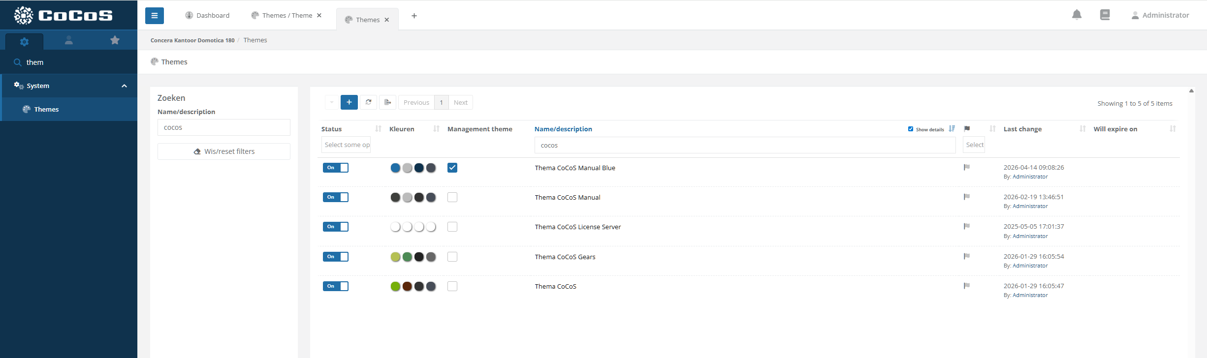
How to create a theme
|
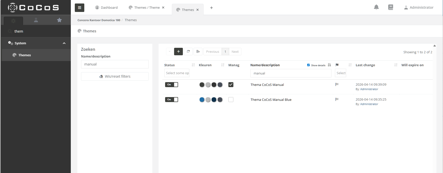
Open the theme collection
Use the menu and navigate to the Theme collection located in the "System" section. |
|
|
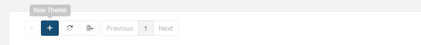
Use the [ + ] button to add a new theme
|
|
|
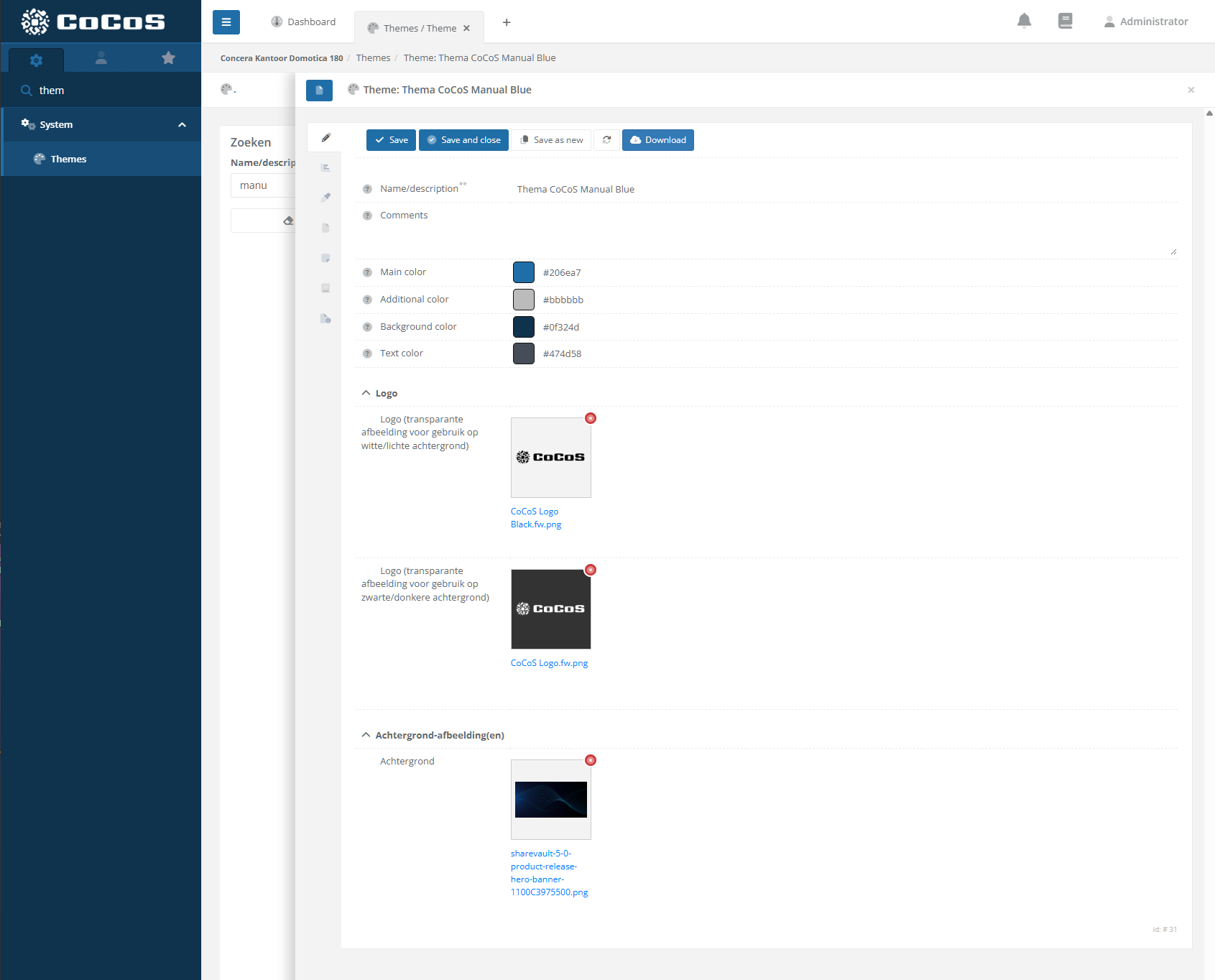
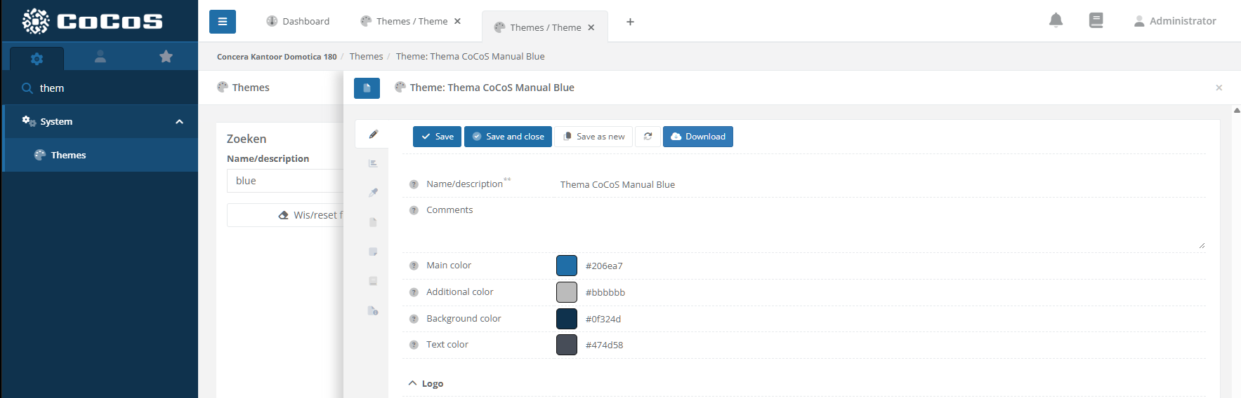
Create a new theme by entering the Name, various colors and images (logo's).
Main Color The main color is used for CoCoS buttons such as [Save], [Save and Close], etc. This color is also used to derive variations when distinction between buttons and related elements is required.
Additional color The additional color is use for color accents like badges, labels etc. Different tints are calculated based on this color and used for a variaty of elements
Background color The background color is used the for background of the menu. The lighter colors are derived from this base color.
Text color
Logo for light backgrounds Described as "Logo (transparante afbeelding voor gebruik op witte/lichte achtergrond)", this logo is used on light backgrounds like on the login screen. Described as "Logo (transparante afbeelding voor gebruik op zwarte/donkere achtergrond)", this logo is used on dark backgrounds like on the menu. Use an image with a transparent background.
Login Background Image Imaged used as background for the login screen of cocos.
When finished, click [Save] to store the theme
To use the theme activate it in the list. |
|
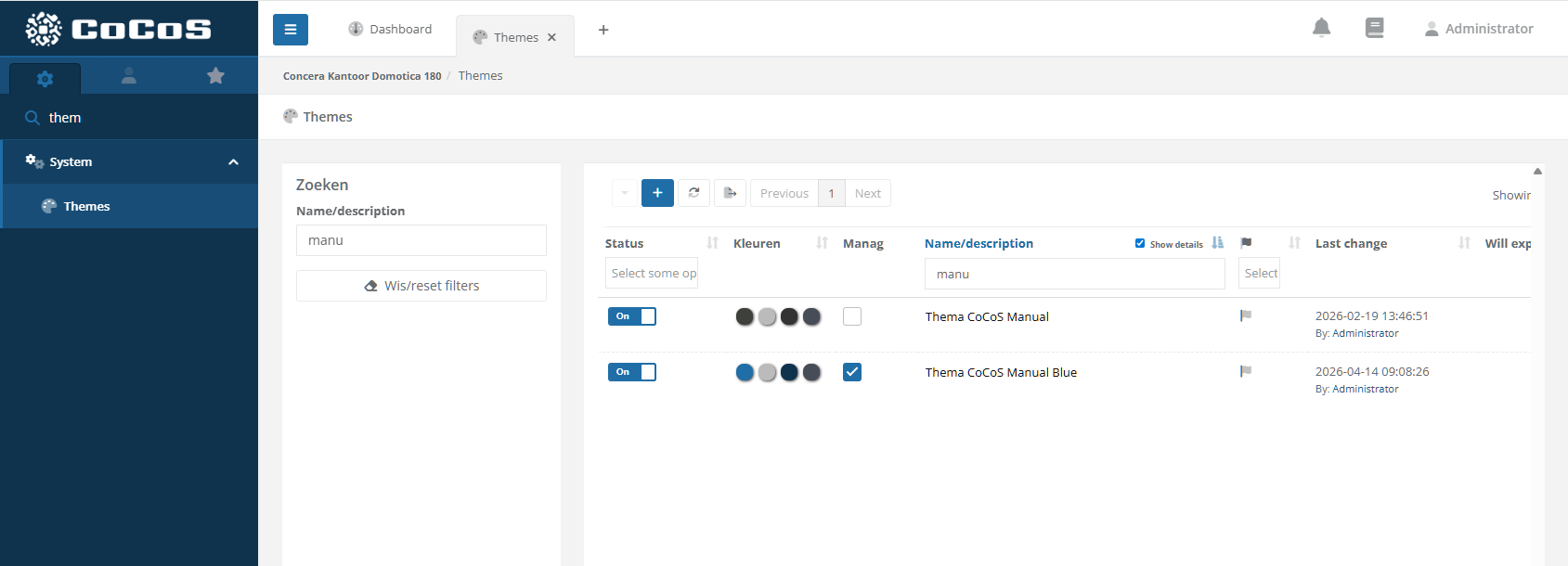
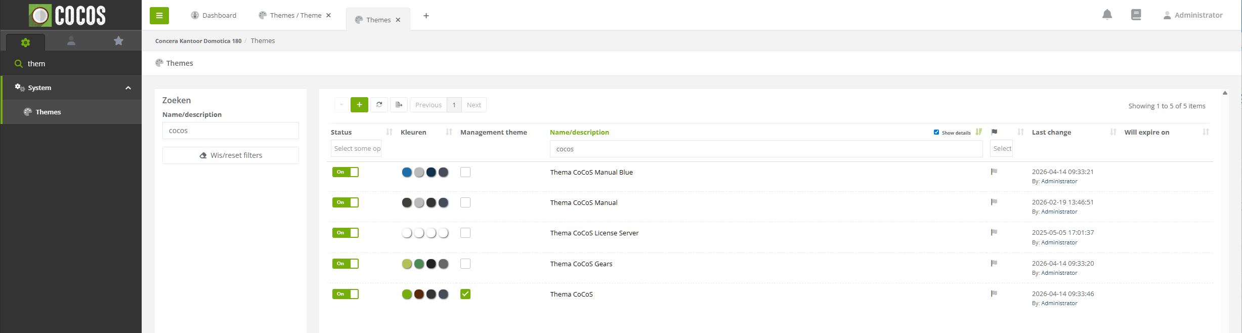
How to activate a theme for use in the management
|
To use a theme for the management, activate the checkbox "Management Theme".
|
|
|
When selected the theme is applied instantly to the management application,
Note, the theme is not yet applied to the login screen. To apply the theme to the login screen a "trusted domain/ip" needs to be entered. |
|
How to export a theme
|
To download a created theme, just hit the [Download] button in the theme.
|
|

How to import a theme
|
To import a theme, just drag and drop the theme that was downloaded from an other system, into the list of the themes.
|
|
|
Enable the Theme and select is for use on the management application by clicking the checkbox in the "management theme" column. The theme wil be applied instantly. |
|
How to allow a theme to be used on the login screen using a trusted domain/ip.
How to control an Output on a MOXA ioLogik using the CoCoS MOXA connector
Question or Case description
This article describes how to configure and control outputs on Moxa ioLogik devices using the new device connector in CoCoS.
The connector replaces the previous script-based method, providing a more user-friendly and reliable way to manage digital inputs and outputs.
Use this article when you want to:
-
Create a Moxa ioLogik device in CoCoS.
-
Control its digital outputs (turn ON/OFF or pulse).
-
Read its input statuses.
Application
The Moxa ioLogik device is typically used to control external systems such as doors, gates, etc.
This setup allows CoCoS to trigger digital outputs through a direct device connector, without the need for custom scripts or webhooks.
How To
Follow the steps below to add and configure the Moxa ioLogik device, and control its outputs.
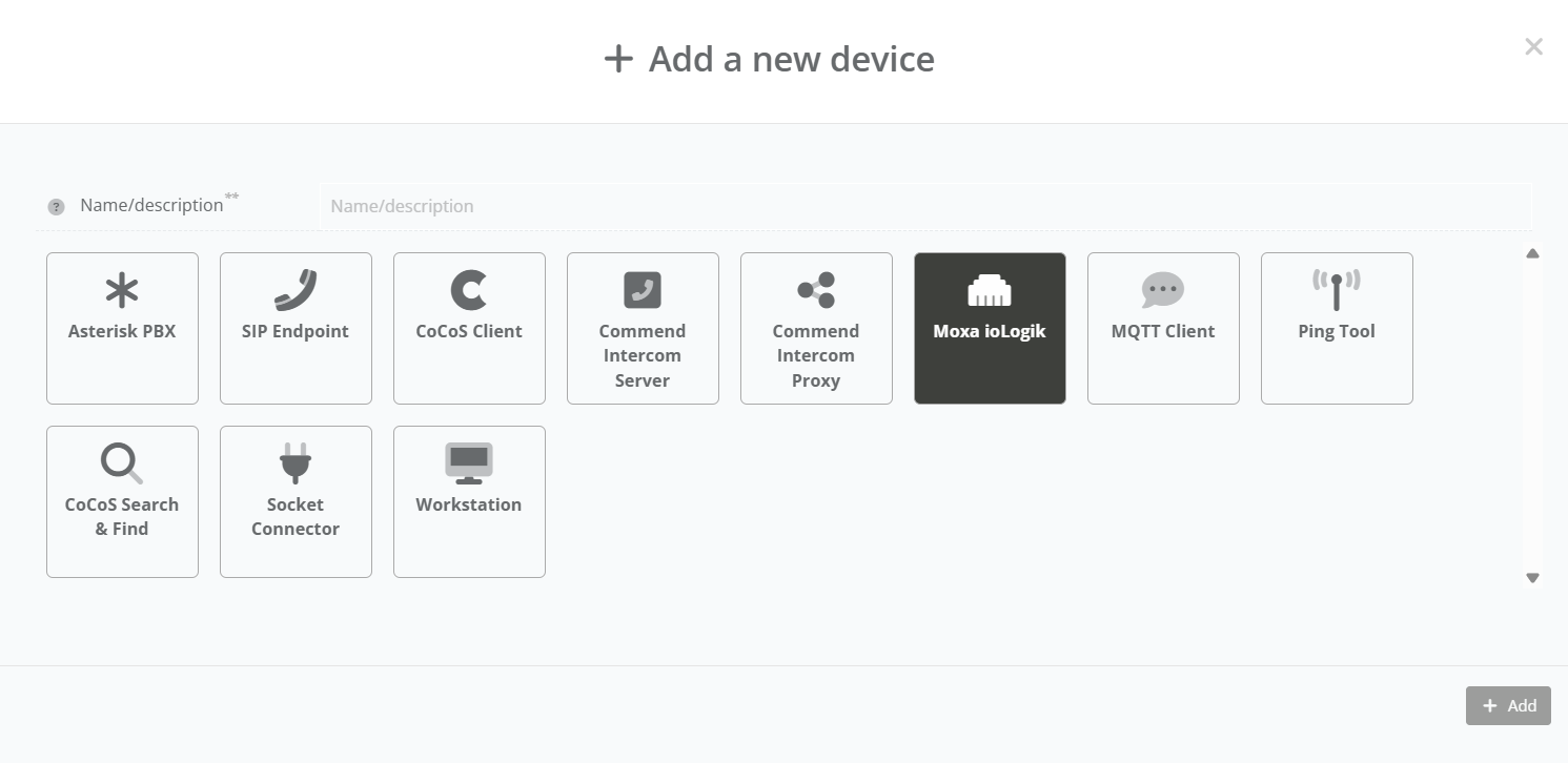
| Step 1: Navigate to "System / Devices", and click on the new device button. |
|
|
Step 2: Enter a clear and descriptive Device Name (for example: “Location - Moxa ioLogik”). |
|
|
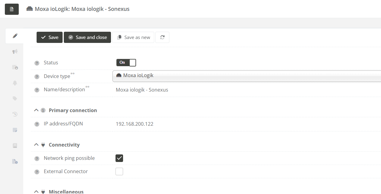
Step 3: In the device configuration panel: |
|
|
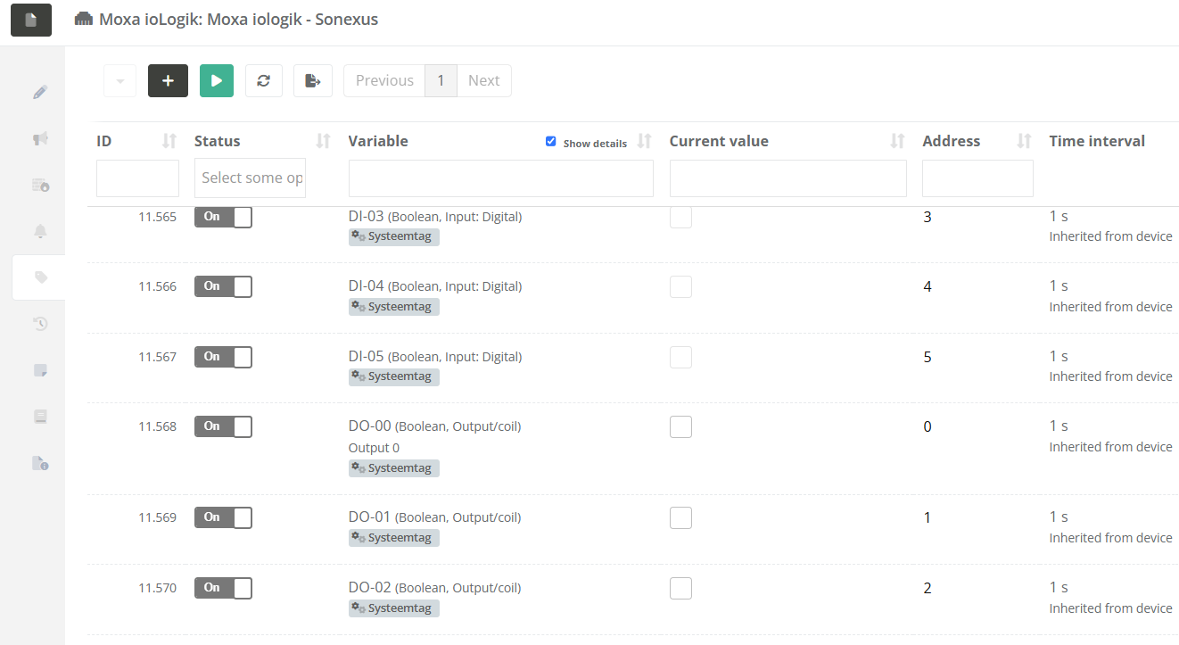
Step 4: After saving, the device will automatically create a list of Tags. These tags represent the available inputs and outputs on the Moxa ioLogik. |
|
|
Step 5: To control an output, use the corresponding tag: - Set the tag value to on / off. - Set the tag value to milliseconds for sending a pulse. |

Validation
To verify that the device and outputs are working correctly:
-
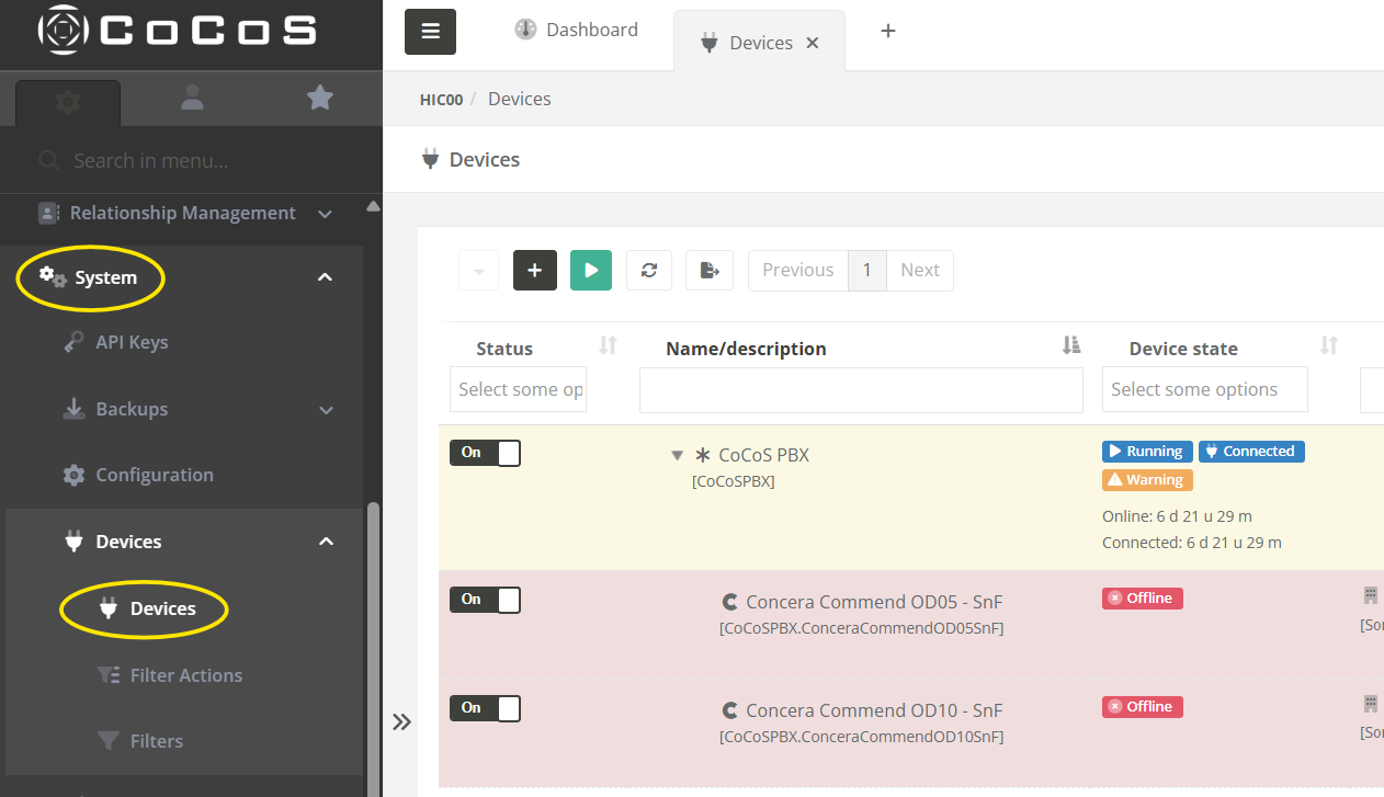
Open the Device view in CoCoS.
- Check that the device shows as Running.
-
Toggle an output and observe the physical response (e.g., relay click, light indicator, or external system activation).
If the device does not respond / has status error:
-
Ensure the IP address and network connection are correct.
-
Confirm that the Moxa ioLogik is powered and reachable.
- Ensure "Restful API" is enabled on the Moxa ioLogik.
References
How to control an Output on a MOXA ioLogik using a CoCoS Script
Please use the custom device type "Moxa ioLogik" instead.
Introduction
This use case describes how to configure a (CoCoS) script for controlling outputs on a MOXA ioLogik device.
Step by step implementation
To configure this use case, follow these steps:
- Create a (Ping) device to represent our MOXA.
- Create a script for handling our MOXA outputs.
- Create relay tag(s) under our device to represent our output(s).
- Testing.
1. Create device
To keep handling of the MOXA relays/outputs on a single place we will create a device for our MOXA by following the following steps:
| Step 1: Navigate to "System / Devices", and click on the new device button. |
|
|
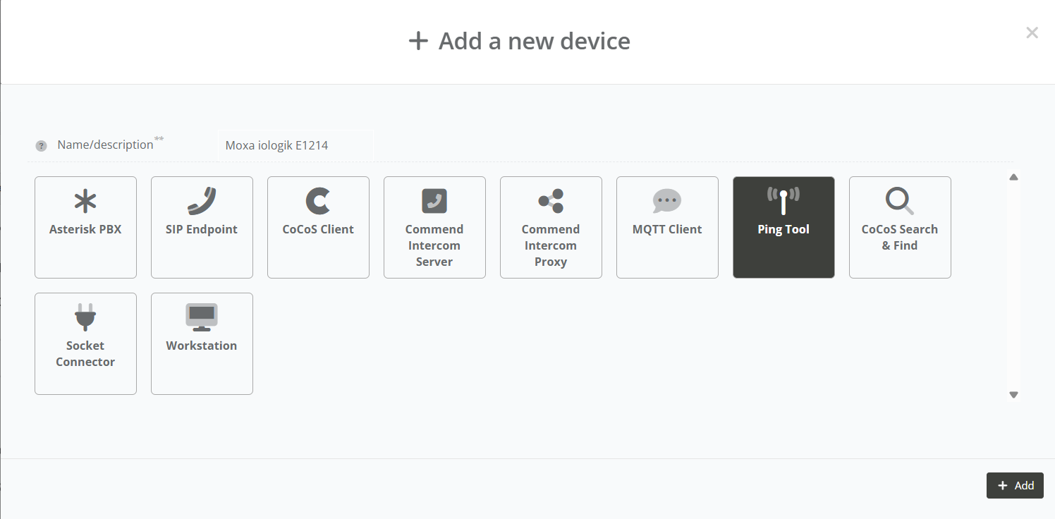
Step 2: Type a name for the device (like: "Location - MOXA ioLogik"), choose the "Ping tool" device type, and click on the add button. |
|
|
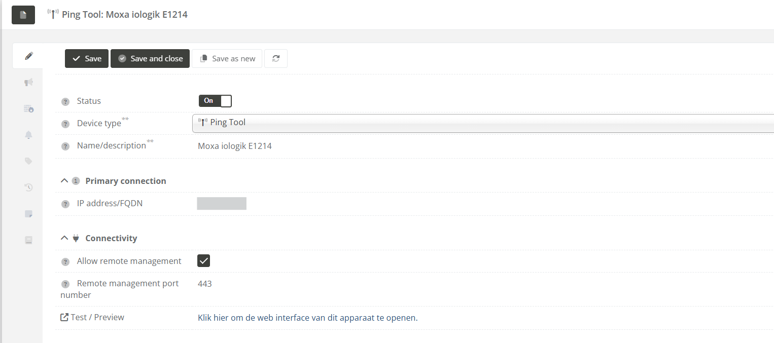
Step 3: Fill in the "IP address" field, set the status to "On", and click on the save button. |
|

2. Create script for output control
For controlling relays/outputs on our MOXA ioLogik we have to create a script.
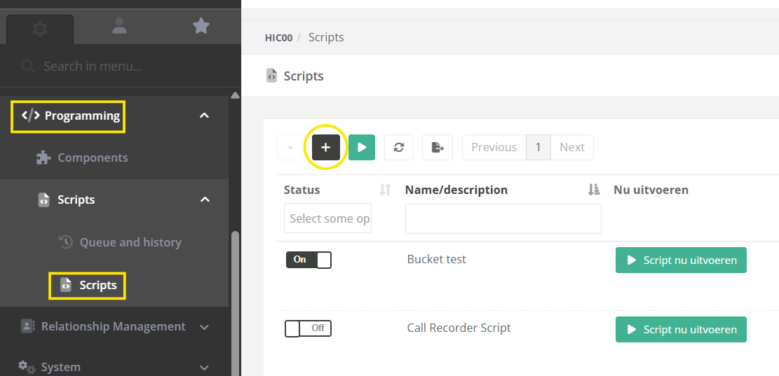
| Step 1: Navigate to "Programming / Scripts" (or "System / Scripts" in versions before 5.1.0), and click on the new script button. |
|
| Step 2: Paste the following script into the "Script" field. |
(See the script bellow) |
The following script can be used for one device, with one or more relay tags (for creating these tags see: 3. Create relay/output tag(s)).
// ---------------------------------------------------------------------
// BASE CONFIGURATION
//
$host = 'x.x.x.x'; // Host / IPAddress of the device to preform
$deviceName = 'MoxaiologikE1214'; // Name of the MOXA device without any spaces
$slot = 0; //
// ---------------------------------------------------------------------
// INIT VARIABLES.
//
// Get the value or use $source to get the tag value from the source tag
if(isset($value) && !empty($value)){
$state = $value;
}
else {
$state = $cocos->tagGet($source);
}
// Get the output/relay to use based on the source tag name
//
$relayTagPrefix = 'device_'.$deviceName.'.relay_';
if(!str_starts_with($source, $relayTagPrefix)) {
$cocos->logError('Invalid $source argument for script. Source \''.$source.'\' does not match required tag name prefix \''.$relayTagPrefix.'\'.');
return;
}
$relay = str_replace($relayTagPrefix, '', $source);
// Prepare our request URL.
// For more info on http request to moxa check: https://www.moxa.com/Moxa/media/PDIM/S100000327/moxa-iologik-e1200-series-manual-v15.2.pdf
$url = 'http://' . $host . '/api/slot/' . $slot . '/io/relay/' . $relay . '/relayStatus';
// ---------------------------------------------------------------------
// CALL THE OUTPUT.
//
// Prepare our request data
$data = json_encode(array(
'slot' => $slot,
'io' => array(
'relay' => array(
$relay => array('relayStatus' => $state)
)
)
), JSON_FORCE_OBJECT);
// Preform the PUT request for setting the relay
$response = $cocos->urlPut($url, $data, 'json', array(
'Accept: vdn.dac.v1',
'Content-Type: application/json',
'Content-Length: ' . strlen($data)
));
// Log output for debugging the script
$cocos->logDebug('PUT ' . $url, "REQ:\nPUT " . $url . "\n> body: " . $data . "\n\nRES:\n" . $response);|
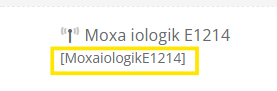
Step 3: Before saving the script change the following variables:
This device name without spaces can be seen under the full device name in the devices list:
|
|
|
Step 4: Give the script a fitting name, and click on the "Save" or "Save and close" button. |
|

3. Create relay/output tag(s)
For our relays/outputs we will now create a (few) tag(s).
The names of these tags must start with relay_ and after that the relay number, since the script we used will use the tag name to identify which relay needs to be switched.
| Step1: Open the device created at 1. Create device, and navigate to the "Taglist" tab. |
|
|
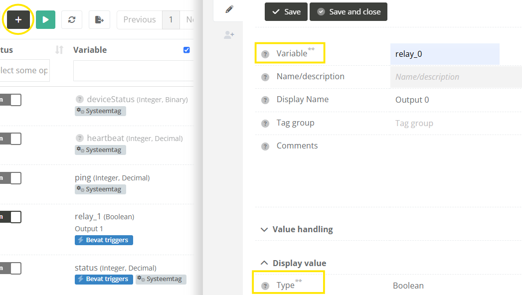
Step 2: Click on the new tag button, and name your tag "relay_<number>". Replace "<number>" with the relay you want to switch. Use 0 when you are unsure, since this relay is used the most in current implementations.
For the tag type, choose "Boolean".
After that click on the "Save" button. |
|
|
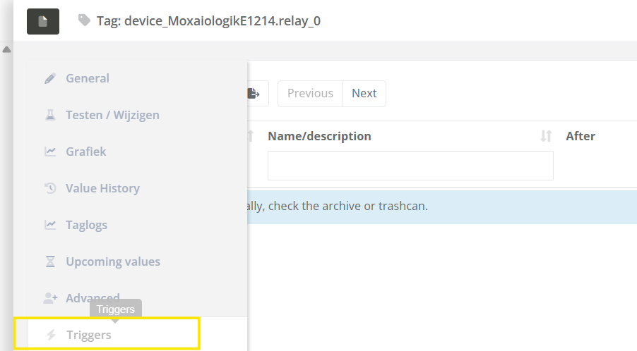
Step 3: Navigate to the "Triggers" tab. |
|
|
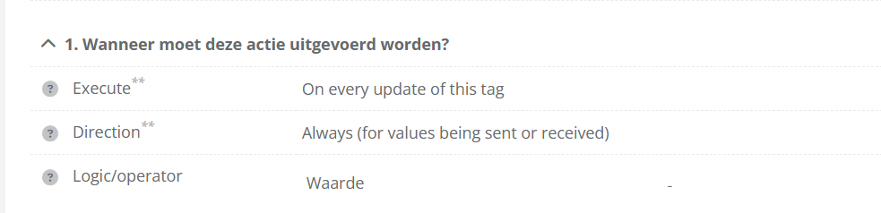
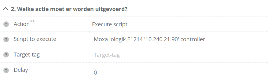
Step 4: Create a trigger that will call the script we created every time the tag has changed (as configured in the image), and click on the "Save" or "Save and close" button.
This will switch the relay to the current tag value. |
|
|
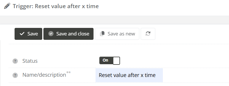
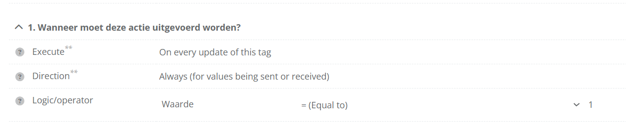
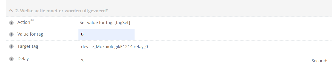
(Optional) Step 5: To make the relay switch back to 0 (off) x seconds after being switched to 1 (on), also add the following trigger (as configured in the image), and click on the "Save" or "Save and close" button. |
|
|
Step 6: Repeat step 3 to 5 for each relay you want to configure. |
|


4. Testing
| Step 1: Click one (or more) of the configured relay tags. |
|
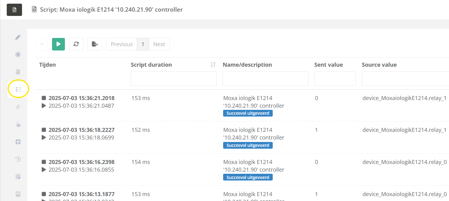
| Step 2: Open the created script, check the "Queue and history" tab to see of the script was executed, and check the "Logbook" tab to see if any issues occurred when executing the script. |
|
How to Control a Relay on a Commend ET908H SIP using a CoCoS Script
Case description
To control an output on a Commend ET908H device we can use the Commend ET908H API. To enable the API / webhooks on the ET908H please consult the device manual. The outputs can used to open a door, open a gate, switch on light etc.
Application
To control an ouput on the ET908H, in an standard IoIP system setup by using and ICX message. But when the ET908H is configured in SIP mode the direct addressing is disabled. To control the output a webrequest is required. Depending on the version of CoCoS, this is done using a direct outbound webhook linked to a trigger, or by using a script that is linked to a trigger or DTMF in a dial plan. This how-to describes the use of a script.
Solution / Resolution / How To
1. Create script for output control
For controlling relays/outputs on our ET908H we have to create a script.
| Step 1: Navigate to "Programming / Scripts" (or "System / Scripts" in versions before 5.1.0), and click on the new script button. |
|
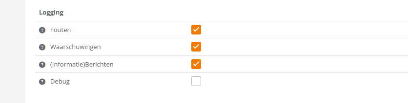
| Step 2: Allow logging of info text in the script. Depending on the CoCoS version, in the settings tab / advanced tab, find the logging section and enable the "Information" checkbox. |
|
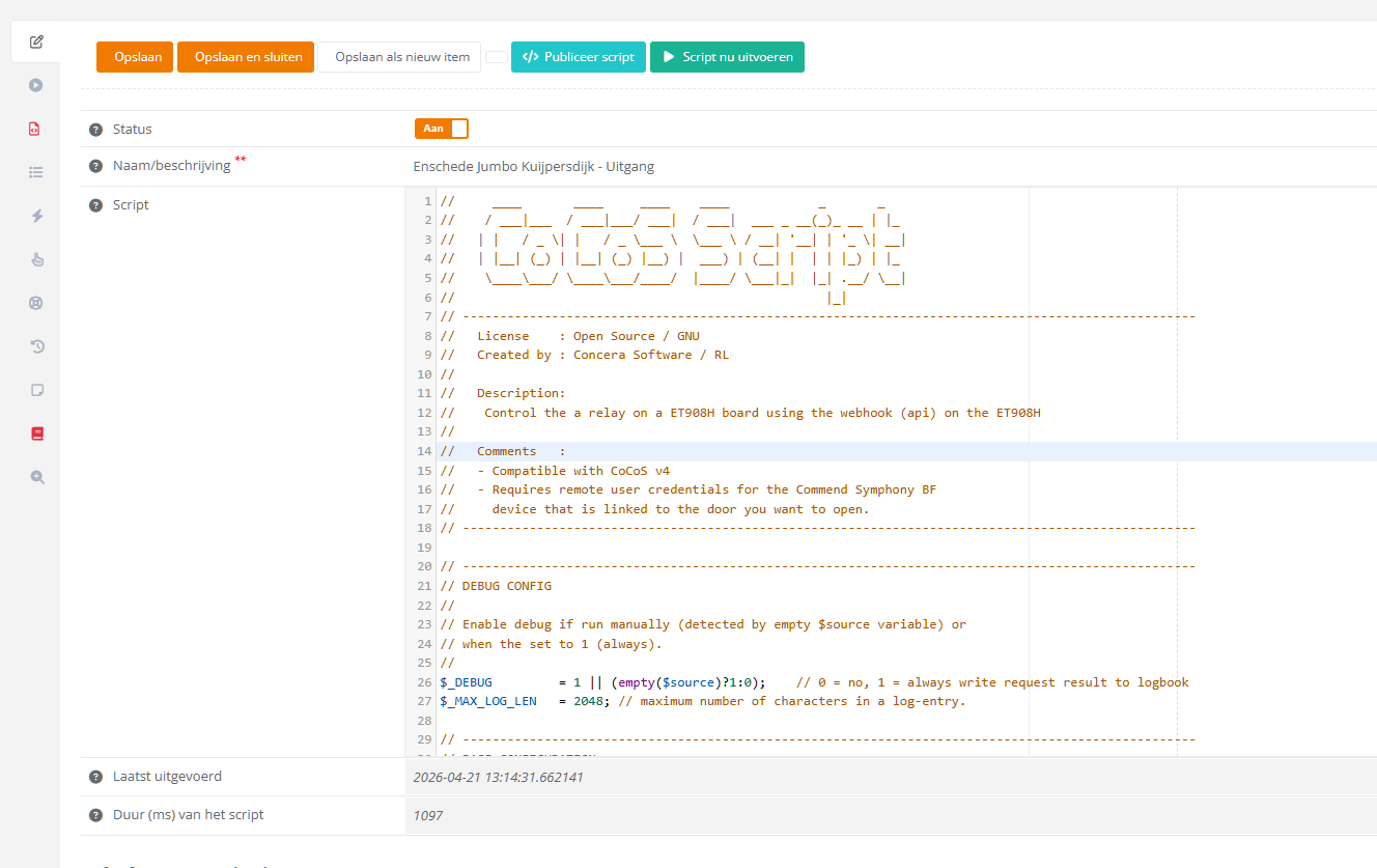
| Setp 3: Enter the script below in the code area. |
|
| Step 4: Save the script using the [ Save ] button. |
|
The following script can be used for one device
// ____ ____ ____ ____ _ _
// / ___|___ / ___|___/ ___| / ___| ___ _ __(_)_ __ | |_
// | | / _ \| | / _ \___ \ \___ \ / __| '__| | '_ \| __|
// | |__| (_) | |__| (_) |__) | ___) | (__| | | | |_) | |_
// \____\___/ \____\___/____/ |____/ \___|_| |_| .__/ \__|
// |_|
// ---------------------------------------------------------------------------------------------------
// License : Open Source / GNU
// Created by : Concera Software / RL
//
// Description:
// Control the a relay on a ET908H board using the webhook (api) on the ET908H
//
// Comments :
// - Compatible with CoCoS v4
// - Requires remote user credentials for the Commend Symphony BF
// device that is linked to the door you want to open.
// ---------------------------------------------------------------------------------------------------
// ---------------------------------------------------------------------------------------------------
// DEBUG CONFIG
//
// Enable debug if run manually (detected by empty $source variable) or
// when the set to 1 (always).
//
$_DEBUG = 1 || (empty($source)?1:0); // 0 = no, 1 = always write request result to logbook
$_MAX_LOG_LEN = 2048; // maximum number of characters in a log-entry.
// ---------------------------------------------------------------------------------------------------
// BASE CONFIGURATION
//
// Device configurations:
$host = '192.168.0.0'; // Host / IPAddress of the device to preform
// the remote action on.
$remoteUsername = 'cocos'; // The username of the remote user account.
$remoteUserPassword = 'password'; // The password of the remote user account.
// Relay configurations:
$relay = 1; // The relay to use for dooropening.
$doorOpenTimeInSeconds = 1; // The time in seconds that indicates how
// long the relay / door must be open for.
// ---------------------------------------------------------------------------------------------------
// INIT VARIABLES.
//
$url = 'https://'.$host.'/cgi-bin/remotecontrol/relais.cgi?relais='.$relay.'&action=dooropener&dooropentimer='.$doorOpenTimeInSeconds;
// ---------------------------------------------------------------------------------------------------
// CALL THE REMOTE DOOROPENER ACTION.
//
$urlGetResult = $cocos->urlGet($url, array(
'Authorization: Basic '. base64_encode($remoteUsername.':'.$remoteUserPassword)
));
// ---------------------------------------------------------------------------------------------------
// WRITE INFO TO LOGBOOK
//
// If debug is enabled by assigning the value 1 or higher to the $_DEBUG variable, the script will
// write call and result data to the logbook with type info.
//
if ($_DEBUG>0){
// clean up result by removing tabs, spaces and line breaks.
$urlGetResult = str_replace("\t","",$urlGetResult); // remove tab
$urlGetResult = str_replace(" " ,"",$urlGetResult); // remove space
$urlGetResult = str_replace("\n","",$urlGetResult); // remove new line
$urlGetResult = str_replace("\r","",$urlGetResult); // remove return
// format single line url and result entry for the logbook.
$info = (empty($source)?"":"SOURCE: ".$source.", ")."URL : $url, RESULT : $urlGetResult";
// log the request and the result.
$cocos->logInfo(substr($info,0,$_MAX_LOG_LEN));
// if the $info string is exceeding the limit of 240 characters.
if (strlen($info)>$_MAX_LOG_LEN){ $cocos->logInfo(substr($urlGetResult,0,$_MAX_LOG_LEN)); }
}2. Test the script
|
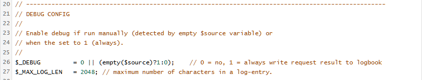
The code on line 26 controls if the script will output data to the logbook. If the script is in debug mode, the script will write the called url and result of the request.
To permanently enable logging, just change the value 0 before the double vertical lines || from 0 to 1. If the value is 0, the script only will run in debug mode when called manually. A manual run is detected by testing the "system" variable $source for content. If empty, the debug mode is enabled automaticly.
|
|
|
Run the script by pressing the [ Run Script ] button. |
|
|
The script is run and will write a line in the logbook. The <code>0</code> in the respons (result) is generated by de Commend ET908H. Please consult the manual for more information on the result code. |
logbook screenshot :
entry : URL : https://10.20.1.3/cgi-bin/remotecontrol/relais.cgi?relais=1&action=dooropener&dooropentimer=1, RESULT : <xmlversion="1.0"encoding="UTF-8"><Response><Code>0</Code><Description>dooropener</Description></Response></xml>
|

References
| Manual for the ET908H setup for dialing via a dial plan with button 0 | Setup Commend ET908H or IM3 for dailing via CoCoS Call Handling (Button.0) |
How to configure IAX Connection
Question or Case description
This article explains how to configure an IAX connection between a CoCoS environment and an external PBX system.
An IAX connection allows calls to be exchanged between CoCoS and another telephone system. This makes it possible for intercoms, SIP devices, and other connected endpoints to communicate between both platforms.
Typical situations where this configuration is used:
- An intercom from an external PBX must be reachable from CoCoS
- Calls from CoCoS must be routed to another PBX
- An existing PBX environment must be integrated with CoCoS
- CoCoS call handling features must be made available to another system
Possible symptoms when the connection is not configured correctly:
- Intercom devices are unreachable
- Calls do not arrive
- Calls disconnect immediately
- The trunk registration fails
- Audio communication is not established
Application
This configuration is commonly used when a CoCoS environment needs to communicate with another PBX using the Inter Asterisk eXchange (IAX) protocol.
Examples include:
- Connecting two PBX systems
- Migrating an existing intercom environment to CoCoS
- Integrating external SIP intercom devices
- Connecting multiple locations through IAX
How To
Requirements
Before starting, verify that the following components are available:
- A working CoCoS environment
- A properly configured CoCoS Asterisk/PBX server
- An external PBX with IAX support
- Network connectivity between both systems
- IAX authentication credentials
Step 1 - Prepare the External PBX
First, configure an IAX trunk on the external PBX.
The exact configuration depends on the PBX vendor, but the following settings are typically required:
| Setting | Value |
| Username | IAX authentication username |
| Password | IAX authentication password |
| Host / IP Address | IP address of the CoCoS environment |
| Port | 4569 |
Important: The username and password must match exactly on both systems.
Step 2 - Create a New IAX Trunk in CoCoS
|
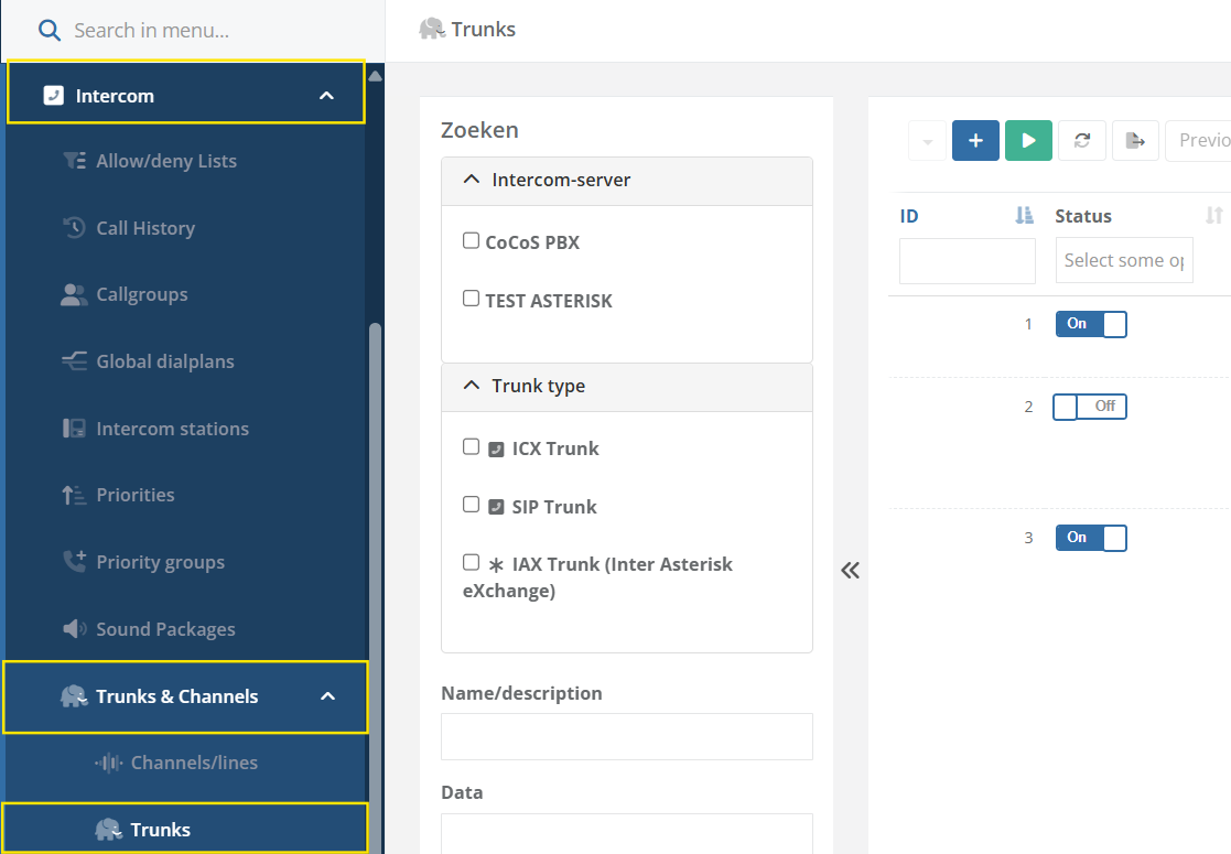
Open the CoCoS Management environment, and navigate to: Intercom → Trunks and Channels → Trunks |
|
|
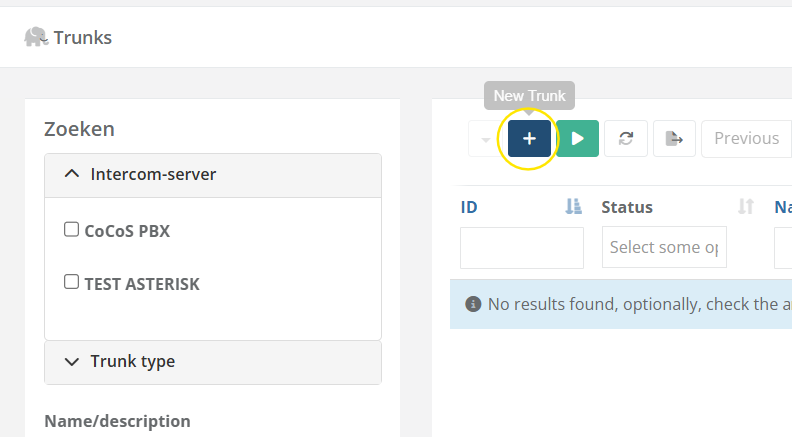
Click the plus icon to create a new trunk. |
|
|
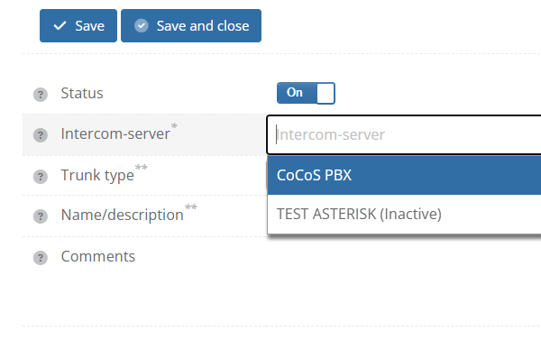
Select the appropriate Asterisk/PBX server in the Intercom Server field. |
|
|
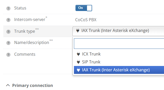
Select the trunk type: Inter Asterisk eXchange Trunk. |
|
|
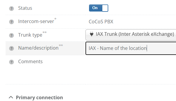
Enter a clear and recognizable name in Name / Description. |
|
Step 3 - Configure the Basic Trunk Settings
|
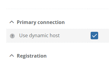
Enable Use Dynamic Host only when a dynamic host configuration is required.
Use this when the extenal PBX is going to connect to CoCoS, which is the case for most use cases currently ) |
|
|
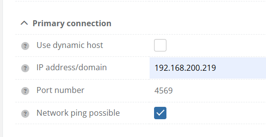
If not using Dynamic Host:
Enter the IP address or domain name of the external PBX in IP Address / Domain, and enter the correct port number. IAX normally uses port 4569. |
|
|
Enter the IAX username in the Username field. |
|
|
Enter the correct password in the Password field. |
|
|
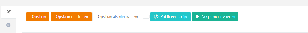
Click Save and Close to store the trunk configuration. |
Step 4 - Link SIP/Intercom Devices to the Trunk
After creating the trunk, the external devices must also be created in CoCoS.
This allows CoCoS to know which calls should be routed through the IAX connection.
|
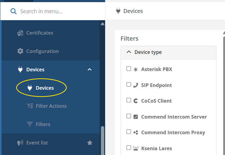
Navigate to: System → Devices |
|
|
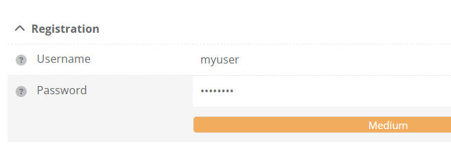
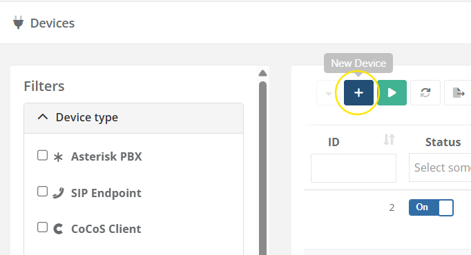
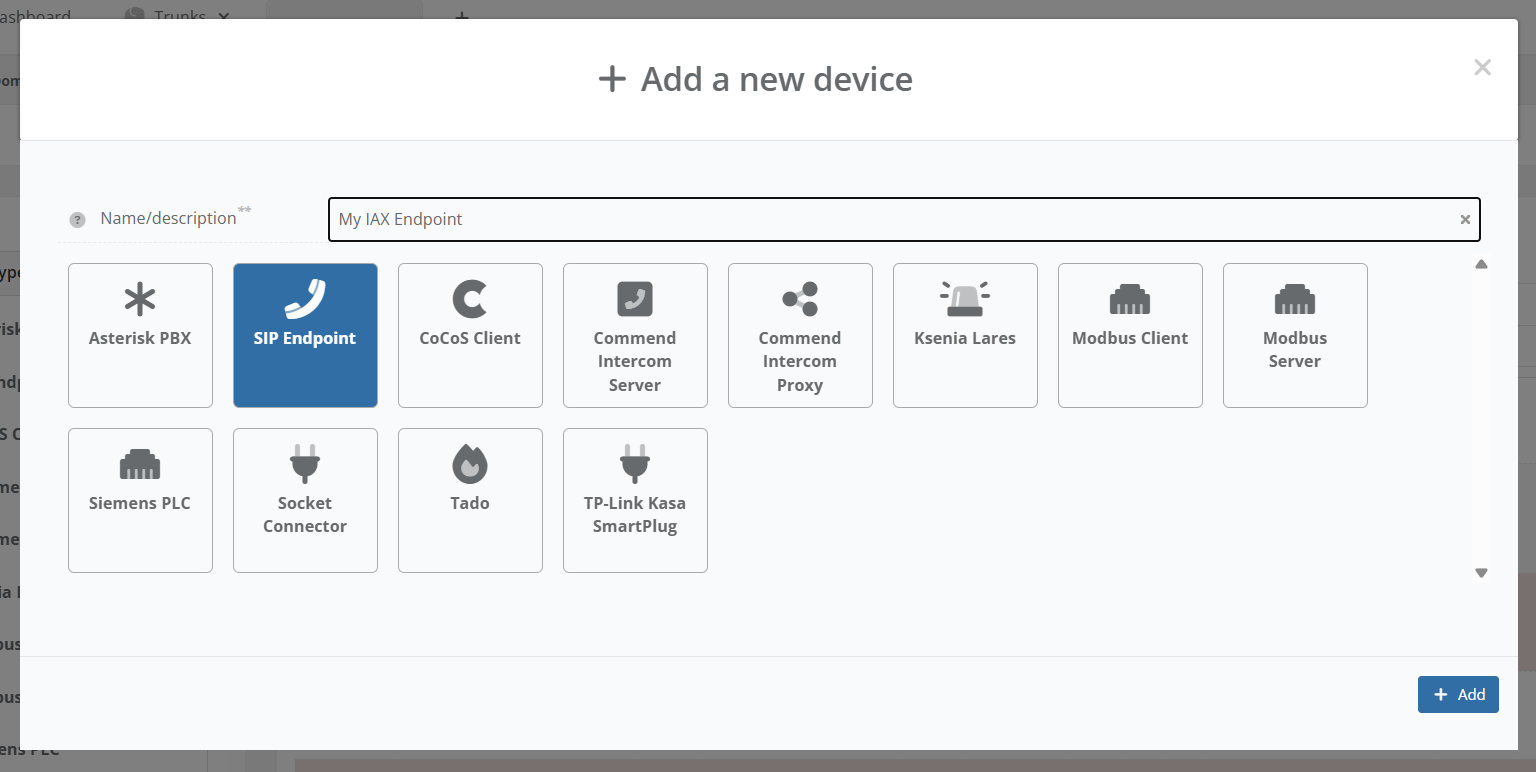
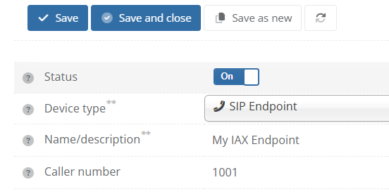
Create a new SIP endpoint device. |
|
|
Enter the extension number of the external device. |
|
|
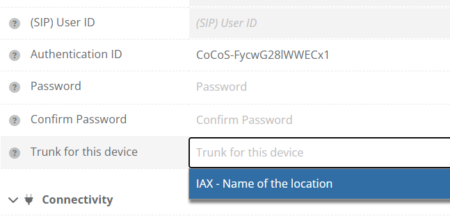
Link the device to the previously created IAX trunk. |
|
|
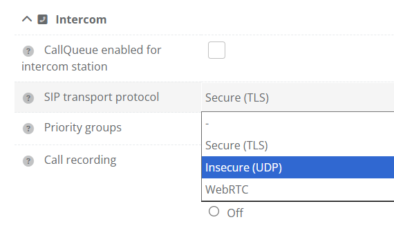
(Optional) You may need to change SIP transport protocol to UDP. |
|
|
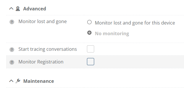
Disable registration monitoring since there is no registration to monitor. |
|
|
Click Save and Close to store the device configuration. |
Repeat these steps for every device that must be reachable through the IAX connection.
Validation
The configuration is considered successful when:
- The trunk registers successfully
- Both systems can reach each other
- Calls work in both directions
- Audio communication functions correctly
- No authentication or other errors appear in the logs
Test Scenario 1 - External PBX to CoCoS
| Test | Expected Result |
| Call a CoCoS intercom from a device on the external PBX. | The CoCoS intercom rings and a call can be established. |
Test Scenario 2 - CoCoS to External PBX
| Test | Expected Result |
| Call a device on the external PBX from a CoCoS intercom. | The external device rings and a call can be established. |
Common Causes of Issues
| Problem | Likely Cause |
| Trunk registration fails | Incorrect username or password |
| No connection possible | Firewall or network restriction |
| Calls fail immediately | Incorrect IP address or port number |
| One-way audio | NAT or firewall configuration |
| Devices unreachable | Endpoint not linked to the trunk |
References
Describe where to find external answers or extra information's